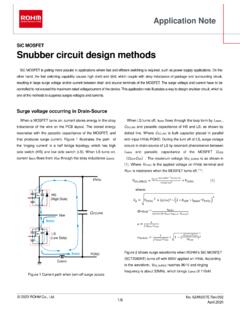
Snubber circuit design methods - Rohm
Snubber circuit design methods Application Note In principle, the snubber has to be placed as close as possible to the MOSFET in order to maximize its effectiveness. (a) C snubber: it has fewer components but has relatively longer wire s. It is more suitable for 2in1 module rather than circuit with discrete components.
Download Snubber circuit design methods - Rohm

Information
Domain:
Source:
Link to this page:
Documents from same domain
SiC Power Devices and Modues Application Note
fscdn.rohm.com600V 400V 100V Si C D D D D G2GG 3ÿ G2GG H 9×3ÿ FÜ SiFÜ 8 æ GG ö G ì e Majority carrier device : High speed Minority carrier device : Low on-resistance, but low speed ・ Significant reduction in recovery loss ・ Downsizing of devices by increase in frequency Can be manufactured in this area, but little advantage over Si
Linear Regulator IC Series Linear Regulator 기초
fscdn.rohm.comLinear Regulator 는 기본적으로 입력, 출력, GND 핀으로 구성되며, 출력이 가변일 경우는 출력전압의 귀환이 필요 하기 때문에 귀환(Feedback)핀이 추가됩니다. (Figure 1) IN OUT FB GND V IN V O Figure 1. Linear Regulator 의 기본구성 Linear Regulator 내부회로의 개요는 Figure 2 …
Op-Amp/Comparator Application Note - Rohm
fscdn.rohm.comop-amp. Generally, an op-amp is composed of three stages: the input stage, the gain stage, and the output stage. The input stage is configured with a differential amplification stage that amplifies the differential voltage between the two terminals. In addition, it does not amplify the common-mode signal component (a condition where no ...
Efficiency of Buck Converter
fscdn.rohm.comEfficiency of Buck Converter Switching regulators are known as being highly efficient power sources. To further improve their efficiency, it is helpful to understand the basic mechanism of power loss. This application note explains power loss factors and methods for calculating them.
Snubber Circuit for Buck Converter IC : Power Management
fscdn.rohm.comSnubber Circuit for Buck Converter IC AEK59-D1-0311-0 For example, when the input voltage VIN is 24 V and the switching frequency fSW is 1 MHz, 2 Ë Ì Ç » L680 pF H24 6 H1 MHz L0.39 W the generated consumption power of 0.39 W requires a 6432 size resistor (2512 in inches) with a rated power of 1 W.
ISO 26262: Functional Safety Standard for Modern Road …
fscdn.rohm.comIntrinsic safety is a method for ensuring safety by removing the causes of danger. Functional safety, on the other hand, is a method of reducing risks to an acceptable level to ensure safety ... verification, prototyping, and evaluation are clarified, with reviews performed at each stage. It is also necessary to manage the documents created at
Calculation of Power Loss (Synchronous) : Power Management
fscdn.rohm.comCalculation of Power Loss (Synchronous) This application note describes how to obtain the power loss required to calculate the temperature of a semiconductor device. Temperature control is important to ensuring product reliability. Figure 1 is a circuit diagram of a synchronous rectification type DC/DC converter. Figure 2 shows a switching node ...
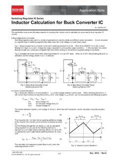
Inductor Calculation for Buck Converter IC
fscdn.rohm.comInductor Calculation of Buck Converter Current-difference between max. and min. (ILP-ILT) is as follows: IN SW D SW IN SW OUT D OUT LP LT V V V L f V V V V V I I (15) Equations (13) and (15) show that large inductance L and high switching frequency will reduce maximum current (ILP)and current difference between max. and min. (ILP-ILT).
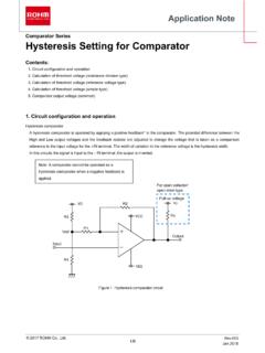
Hysteresis Setting for Comparator - Rohm
fscdn.rohm.comprovided only to illustrate the standard usage and operations of the Products. The peripheral conditions must be taken into account when designing circuits for mass production. The technical information specified herein is intended only to show the typical functions of and examples of application circuits for the Products.

ROHM Switching Regulator Solutions Synchronous Buck ...
fscdn.rohm.comROHM Switching Regulator Solutions Synchronous Buck Converter Controller BD9611MUV-EVK-001 Description Using a synchronous rectified step-down DC/DC converter IC BD9611MUV BD 9611MUV-EVK-001 evaluation board 15.0 V ~ output a 24 V input voltage 12.0 V. Provides 10.0A output current. Output current is possible with current settings by selecting
Related documents

STATISTICAL METHODS FOR QUALITY CONTROL
www.swlearning.comStatistical Methods for Quality Control 5 fies the scale of measurement for the variable of interest. Each time a sample is taken from the production process, a value of the sample mean is computed and a data point show-

RESEARCH SERIES Observational research methods. …
emj.bmj.comonly methods available. The objective of most clinical studies is to determine one of the following—prevalence,inci-dence, cause, prognosis, or effect of treatment; it is therefore useful to remember which type of study is most commonly associated with each objective (table 1) While an appropriate choice of study design is vital, it is not ...

Research Methods, Design, and Analysis - Pearson
www.pearsonhighered.comResearch Methods, Design, and Analysis TWELFTH EdiTion Larry B. Christensen University of South Alabama R. Burke Johnson University of South Alabama Lisa A. Turner University of South Alabama Boston Columbus Indianapolis New York San Francisco Upper Saddle River Amsterdam Cape Town Dubai London Madrid Milan Munich Paris Montréal Toronto

CHOOSING A MIXED METHODS DESIGN - SAGE …
www.sagepub.comThe most common and well-known approach to mixing methods is the Triangulation Design (Figure 4.1a) (Creswell, Plano Clark, et al., 2003). The pur-pose of this design is “to obtain different but complementary data on the same topic” (Morse, 1991, p. 122) to best understand the research problem. The intent

Quasi-Experimental Design and Methods - unicef-irc.org
www.unicef-irc.orgMethodological Brief No.8: Quasi-Experimental Design and Methods Page 4 Figure 1. Example of a distribution of propensity scores – region of common support is 0.31 to 0.80 Source: Data created by authors for illustrative purposes only. Figure 1 shows a typical distribution of propensity scores. The distribution for the treatment group is