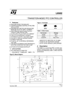
Transition-mode PFC controller - STMicroelectronics
DESKTOP PC, MONITOR) UP TO 300W – HI-END AC-DC ADAPTER/CHARGER – ENTRY LEVEL SERVER & WEB SERVER 2 Description The L6562 is a current-mode PFC controller oper-ating in Transition Mode (TM). Pin-to-pin compati-ble with the predecessor L6561, it offers improved performance. TRANSITION-MODE PFC CONTROLLER Figure 2. Block Diagram + …
Download Transition-mode PFC controller - STMicroelectronics

Information
Domain:
Source:
Link to this page:
Documents from same domain

Low-power dual operational amplifier - st.com
www.st.comFebruary 2016 DocID2471 Rev 17 1/24 This is information on a product in full production. www.st.com LM2904, LM2904A Low-power dual operational amplifier

AN3128 Application note - st.com
www.st.comJune 2011 Doc ID 16918 Rev 5 1/105 AN3128 Application note STM32 embedded graphic objects/touchscreen library Introduction This library is a firmware package which contains a collection of routines, data structures,

AN4767 Application note - st.com
www.st.comDocID028380 Rev 2 7/16 AN4767 Dual bank use cases 15 With dual bank, all the manipulation with the other bank is just another task of the main program.

AN3155 Application note - st.com
www.st.comOctober 2016 DocID17066 Rev 7 1/37 1 AN3155 Application note USART protocol used in the STM32 bootloader Introduction This application note describes the USART protocol used in the STM32 microcontroller

USB Power Delivery and Type-C - st.com
www.st.comUSB Type -C Overview USB Power Delivery specification introduces USB Type-C receptacle, plug and cable; they provide a smaller, thinner and more robust alternative to existing USB interconnect.

Datasheet - L78 - Positive voltage regulator ICs - …
www.st.comTO- 2 2 0 TO-2 2 0 F P DPAK D² PAK Features • Output current up to 1.5 A • Output voltages of 5; 6; 8; 8.5; 9; 12; 15; 18; 24 V • Thermal overload protection

AN2867 Application note - st.com
www.st.comMay 2017 DocID15287 Rev 11 1/43 1 AN2867 Application note Oscillator design guide for STM8AF/AL/S and STM32 microcontrollers Introduction Many designers know oscillators based on Pierce-Gate topology (hereinafter referred to as

AN4776 Application note - st.com
www.st.comMay 2017 DocID028459 Rev 2 1/73 1 AN4776 Application note General-purpose timer cookbook Introduction The timer peripheral is part of …

120-volt, 100-watt, DMOS audio amplifier with mute …
www.st.comSeptember 2010 Doc ID 6744 Rev 8 1/21 21 TDA7293 120-volt, 100-watt, DMOS audio amplifier with mute and standby Features Multipower BCD technology Very high operating voltage range (±50 V)

Electronic transformer for a 12V halogen lamp - …
www.st.comAPPLICATION NOTE AN528/0999 1/4 ELECTRONIC TRANSFORMER FOR A 12V HALOGEN LAMP by P. Fichera, R. Scollo 1. INTRODUCTION Lighting that uses halogen lamps is commonly found
Related documents
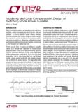
AN149 Modeling and Loop Compensation Design of …
www.analog.comsystem, the 3-terminal PWM cell averagemodelingmethod can be applied by changing the active switch Q to an aver-aged current source and the passive switch (diode) D to an averaged voltage source. The averaged switch Q current equals d • iL and the averaged switch D voltage equals d • vap, as shown in Figure 5. The averaging is applied

Arduino PWM and Analog Output - halvorsen.blog
www.halvorsen.blogPulse-Width Modulation (PWM) •The Arduino's programming language makes PWM easy to use; simply call analogWrite(pin, dutyCycle), where dutyCycleis a value from 0 to 255, and pin is one of the PWM pins (3, 5, 6, 9, 10, or 11). •The analogWritefunction provides a simple interface to the hardware PWM, but doesn't provide any control over ...
Introduction to Switch Mode Power Supplies (SMPS)
www.microchip.comnext pwm cycle. If the current was to drop to zero, then the control mode is called “Discontinuous”. The discontinuous mode of operation can be more difficult to control than the “Continuous” mode where the current through the inductor is always greater than zero. The choice of the inductor value relative to the pwm frequency is important.
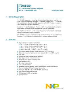
TDA8954 2 × 210 W class-D power amplifier - NXP
www.nxp.comsuppressed by disabling the voltage-to-current (VI) converter input stages • Operating mode: the amplifier is fully operational, de-muted and can deliver an output signal A slowly rising voltage should be applied (e.g. via an RC network) to pin MODE to ensure pop noise-free start-up. The bias-current setting of the (VI converter) input stages is

NCP1252 - Current Mode PWM Controller for Forward and ...
www.onsemi.comCurrent Mode PWM Controller for Forward and Flyback Applications The NCP1252 controller offers everything needed to build cost− effective and reliable ac−dc switching supplies dedicated to ATX power supplies. Thanks to the use of an internally fixed timer, NCP1252 detects an output overload without relying on the auxiliary Vcc.

UC3842B - High Performance Current Mode Controllers
www.onsemi.comCurrent Mode Controllers UC3842B, UC3843B, UC2842B, UC2843B ... • Latching PWM for Cycle−By−Cycle Current Limiting ... This device contains latch-up protection and exceeds 100 mA per JEDEC Standard JESD78. UC3842B, UC3843B, UC2842B, UC2843B www.onsemi.com 3

Solar charge controller User Manual - TME
www.tme.euGreater than 1.2 times the rated current of 10 seconds or greater than 1.5 times the rated current for 1 second overload start. Greater than 2.9 times the rated current,short circuit protection action,reaction time 5-8Us. Soft start time 0.8s (PWM=0-100%) No-load loss 8-22mA (Indicator light when) Charging circuit resistance 6-18mR