
VOLTAGE TRANSFORMERS
rated voltages, and the value of C2 is varied by the use of auxiliar y capacitance to maintain ... the actual loading on a particular device under unbalanced voltage conditions, as when short circuits occur, certain conversions must be made. This is described later in more
Download VOLTAGE TRANSFORMERS

Information
Domain:
Source:
Link to this page:
Documents from same domain
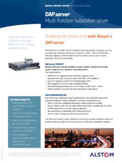
DIGITAL CONTROL SYSTEM PRODUCT SOLUTIONS …
www.gegridsolutions.comUnlock the value of your substation data with Alstom™s multi-function substation server DIGITAL CONTROL SYSTEM PRODUCT SOLUTIONS DAPserver Multi-function substation server
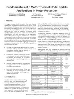
Fundamentals of a Motor Thermal Model and its …
www.gegridsolutions.comMotor Thermal Model Protection Applications 41 1. Abstract This paper discusses the fundamentals of a motor thermal model and its mathematical interpretation and physics for the
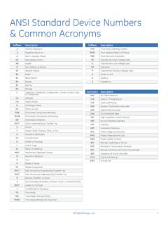
ANSI Standard Device Numbers & Common …
www.gegridsolutions.comGEDigitalEnergycom 1 ANSI Standard Device Numbers & Common Acronyms Suffixes Description _1 Positive-Sequence _2 Negative-Sequence A Alarm, Auxiliary Power AC Alternating Current ...
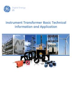
Instrument Transformer Basic Technical …
www.gegridsolutions.comg ITI Digital Energy Instrument Transformer Basic Technical Information and Application
MiCOM P543, P544, P545, P546 - GE Grid Solutions
www.gegridsolutions.comMiCOM P543, P544, P545, P546 Technical Manual Current Differential Relays Platform Hardware Version: K Platform Software Version: …
NERC Critical Infrastructure Protection: Cyber Asset ...
www.gegridsolutions.comNERC Critical Infrastructure Protection: Cyber Asset Protection. 7. 1. Introduction. The NERC Critical Infrastructure Protection Committee (CIPC)

469 Motor Management Relay - GE Grid Solutions
www.gegridsolutions.comtoc table of contents 469 motor management relay – instruction manual toc–i table of contents 1: getting started important procedures ..... 1-1
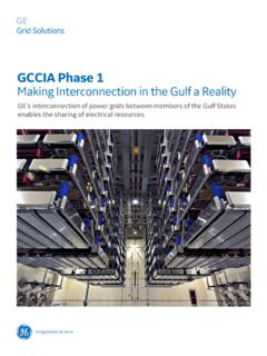
GCCIA Phase 1 - GE Grid Solutions
www.gegridsolutions.comThe GCCIA is an organisation formed in July 2001 in order to create an integrated and sustainable energy economy amongst the six Gulf States. MakinG interconnection in the Gulf a reality GCCIA Phase 1
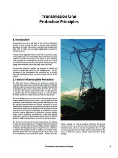
Transmission Line Protection Principles - GE Grid …
www.gegridsolutions.comTransmission Line Protection Principles 7 1. Introduction Transmission lines are a vital part of the electrical distribution system, as they provide the …
Transformer Protection Principles - GE Grid Solutions
www.gegridsolutions.comTransformer Protection Principles 47 phase shift of the protected transformer. Traditional installations may use delta-connected or wye-connected CTs that externally
Related documents
A Test Bench for Differential Circuits - Designer’s Guide
designers-guide.orgA Test Bench for Differential Circuits The New Test Bench 4 of 7 The Designer’s Guide Community www.designers-guide.org Notice that In these equations, ip and in defy normal convention and are positive as they exit their pins so that the current at one side of the balun matches the direction at the

Testing of Power Transformers - ABB
library.e.abb.comA 10.2 Generation of high impulse voltages 177 A 10.3 Pre-calculation of impulse waveform 180 A 10.4 Test circuit parameters for switching impulse test 183 A 10.5 Measuring high impulse voltages 183 A 10.6 Calibrating the impulse voltage divider ratio 190 A 10.7 Use of a Sphere-gap for checking the scale factor of an impulse peak voltmeter 190
Transformer Protection Application Guide
site.ieee.org(27) or unbalanced voltage detection (47). If there is local generation, to help detect islanding conditions an over/under frequency (81, O/U) relay may be installed, though an 81 may not be considered a transformer protection element. Directional overcurrent relays and directional power (67/50, 67/51, and 32, respectively,

Precision Thermocouple Amplifiers with Cold Junction ...
www.analog.comand AD8497 require supply voltages larger than 5 V or a negative voltage applied to the reference pin. Measurement junction temperatures below 5°C require either a ... 6 Unbalanced supplies can also be used. Care should be taken that the common-mode voltage of the thermocouple stays within the input voltage range of the part.

Digital VLSI Design Lecture 1: Introduction
www.eng.biu.ac.il• Unbalanced rising/falling delays will result in unwanted skew. • Special “clock cells” are designed with balanced rising/falling delays to minimize skew. • These cells are usually less optimal for data and so should not be used. •In general, only buffers/inverters should be used on clock nets • But sometimes, we need gating logic.

Understanding Hot-Wire Anemometry - Mouser Electronics
www.mouser.combecome unbalanced, resulting in a voltage difference between points 1 and 2. The amplifier detects this difference. It adjusts the feedback current accordingly to keep the wire temperature and resistance constant, and thus re-balances the bridge. These changes in current can be measured and used to calculate the flow velocity over the wire.