Transcription of VOLTAGE TRANSFORMERS
1 118 VOLTAGE TRANSFORMERSTwo types of VOLTAGE transformer are used for protective-relaying purposes, as follows: (1)the "instrument potential transformer," hereafter to be called simply "potentialtransformer," and (2) the "capacitance potential device." A potential transformer is aconventional transformer having primary and secondary windings. The primary windingis connected directly to the power circuit either between two phases or between one phaseand ground, depending on the rating of the transformer and on the requirements of theapplication. A capacitance potential device is a VOLTAGE -transforming equipment using acapacitance VOLTAGE divider connected between phase and ground of a power OF POTENTIALTRANSFORMERSThe ratio and phase-angle inaccuracies of any standard ASA accuracy class1of potentialtransformer are so small that they may be neglected for protective-relaying purposes if theburden is within the "thermal" volt-ampere rating of the transformer.
2 This thermalvolt-ampere rating corresponds to the full-load rating of a power transformer. It is higherthan the volt-ampere rating used to classify potential TRANSFORMERS as to accuracy formetering purposes. Based on the thermal volt-ampere rating, the equivalent-circuitimpedances of potential TRANSFORMERS are comparable to those of "burden" is the total external volt-ampere load on the secondary at rated secondaryvoltage. Where several loads are connected in parallel, it is usually sufficiently accurateto add their individual volt-amperes arithmetically to determine the total a potential transformer has acceptable accuracy at its rated VOLTAGE , it is suitable over therange from zero to 110% of rated less VOLTAGE .
3 Operation in excess of 10% overvoltage maycause increased errors and excessive precise accuracy data are required, they can be obtained from ratio-correction-factor curves and phase-angle-correction curves supplied by the TRANSFORMERSVOLTAGE TRANSFORMERS 119 CAPACITANCE POTENTIAL DEVICESTwo types of capacitance potential device are used for protective relaying: (1) the"coupling-capacitor potential device," and (2) the "bushing potential device." The twodevices are basically alike, the principal difference being in the type of capacitance voltagedivider used, which in turn affects their rated burden.
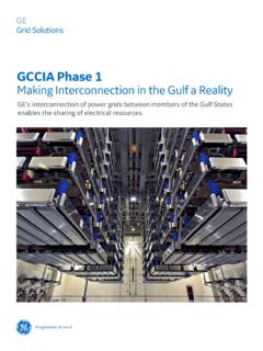
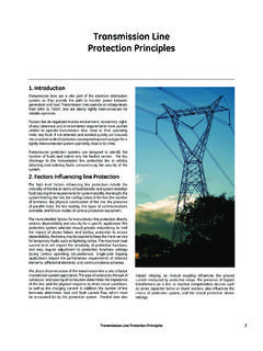
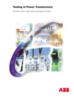
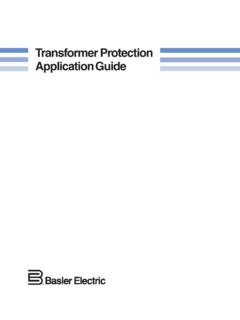
4 The coupling-capacitor device usesas a VOLTAGE divider a "coupling capacitor" consisting of a stack of series-connectedcapacitor units, and an "auxiliary capacitor," as shown schematically in Fig. 1. Thebushing device uses the capacitance coupling of a specially constructed bushing of acircuit breaker or power transformer, as shown schematically in Fig. of these relaying potential devices are called "Class A" are alsosometimes called "In-phase" or "Resonant" devices3for reasons that will be evident types of potential devices, called "Class C" or "Out-of-phase" or "Non-resonant," arealso described in References 2 and 3, but they are not generally suitable for protectiverelaying, and therefore they will not be considered further 1 Coupling-capacitor VOLTAGE dividerFig.
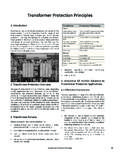
5 2 Capacitance-bushing VOLTAGE VOLTAGE TRANSFORMERSA schematic diagram of a Class A potential device including the capacitance voltagedivider is shown in Fig. 3. Not shown are the means for adjusting the magnitude and phaseangle of the secondary VOLTAGE ; the means for making these adjustments vary with differentmanufacturers, and a knowledge of them is not essential to our present purposes. TheClass A device has two secondary windings as shown. Both windings are rated 115 volts,and one must have a tap. These windings are connected in combination with thewindings of the devices of the other two phases ofa three-phase power circuit.
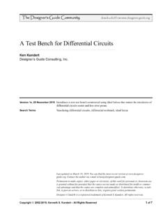
6 The connection is"wye" for phase relays and "broken delta" forground relays. These connections will beillustrated later. The equivalent circuit of a Class Adevice is shown in Fig. 4. The equivalent reactanceXL, is adjustable to make the burden VOLTAGE VBbein phase with the phase-to-ground VOLTAGE of thesystem VS. The burden is shown as a resistorbecause, so far as it is possible, it is the practice tocorrect the power factor of the burdenapproximately to unity by the use of auxiliarycapacitance burden. When the device is properlyadjusted,XC1XC2XL= (1)XC1+XC2which explains why the term "Resonant" is applied to this device.
7 Actually, XC2is so smallcompared with XC1 that XL is practically equal to XC2. Therefore, XLand XC2would bepractically in parallel resonance were it not for the presence of the burden 3. Schematic diagram of a Class A potential 4 Equivalent circuit of a Class Apotential TRANSFORMERS121 The gross input in watts from a power circuit to a capacitance potential-device network is:3W = 2 C1 VSV2sin watts(2)where = power-system frequency. = phase angle between VSand V2C1= capacitance of main capacitor (see Fig. 3) in V2are volts defined as in Fig. 4. If the losses in the network are neglected, equation2 will give the output of the device. For special applications, this relation is useful forestimating the rated burden from the known rated burden under standard conditions; itis only necessary to compare the proportions in the two cases, remembering that, for agiven rating of equipment, the tap VOLTAGE V2varies directly as the applied VOLTAGE a given group of coupling-capacitor potential devices, the product of the capacitanceof the main capacitor C1and the rated circuit- VOLTAGE value of VSis practically constant; inother words, the number of series capacitor units that comprise C1is approximatelydirectly proportional to the rated circuit VOLTAGE .
8 The capacitance of the auxiliarycapacitor C2is the same for all rated circuit voltages, so as to maintain an approximatelyconstant value of the tap VOLTAGE V2for all values of rated circuit bushing potential devices, the value of C1is approximately constant over a range ofrated voltages, and the value of C2is varied by the use of auxiliary capacitance to maintainan approximately constant value of the tap VOLTAGE V2for all values of rated circuit RATED BURDENS OF CLASS A POTENTIAL DEVICESThe rated burden of a secondary winding of a capacitance potential device is specified inwatts at rated secondary VOLTAGE when rated phase-to-ground VOLTAGE is impressed acrossthe capacitance VOLTAGE divider.
9 The rated burden of the device is the sum of the wattburdens that may be impressed on both secondary windings capacitors are provided in the device for connecting in parallel with theburden on one secondary winding to correct the total-burden power factor to unity orslightly VOLTAGE TRANSFORMERSThe standard2rated burdens of bushing potential devices are given in Table 1. Rated Burdens of Bushing Potential DevicesRated CircuitVoltage, kvRated Burden,--------------------------------- --------------------------------Phase-to -Phase Phase-to-Ground watts115 25138 35161 45230 80287 100 The rated burden of coupling-capacitor potential devices is 150 watts for any of the ratedcircuit voltages.
10 Including those of Table ACCURACY OF CLASS A POTENTIAL DEVICEST able 2 gives the standard maximum deviation in VOLTAGE ratio and phase angle for ratedburden and for various values of primary VOLTAGE , with the device adjusted for the specifiedaccuracy at rated primary 2. Ratio and Phase-Angle Error versus VoltageMaximum DeviationPrimary VOLTAGE ,-------------------------------- ---------------------------------------- ---------percent of rated Ratio, percent Phase Angle, degrees100 3 gives the standard maximum deviation in VOLTAGE ratio and phase angle for ratedvoltage and for various values of burden with the device adjusted for the specified accuracyat rated 3.