Transcription of SRF005 U LTRASONIC R S - Home - PICAXE
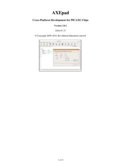
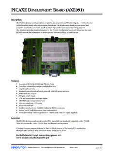
1 SRF005 ULTRASONIC RANGE SENSOR revolutionRevolution Education Ltd. Email: Web: 02 :The SRF005 ultrasonic range sensor detects objects in it s path and can be used tocalculate the range to the object. It is sensitive enough to detect a 3cm diameterbroom handle at a distance of over 5 VCurrent- 30mA Typ. 50mA 40 KHzMax Range- 3 mMin Range- 3 cmSensitivity- Detect 3cm diameter broom handle at > 3 mInput Trigger- 10uS Min. TTL level pulseEcho Pulse- Positive TTL level signal, width proportional to Size- 43mm x 20mm x 17mm heightThe module can be used in two different modes:Single Pin- Single microcontroller pin (08M, and all M2 and X2 parts)Dual Pin- Separate PICAXE microcontroller trigger and echo pinsMost users using the latest generation (M2 and X2) PICAXE parts should select single pin connection Pin Connection Mode:The PICAXE -08M and all M2/X2 parts have bi-directional pins, so the SRF005 canconnect to a single i/o are two way to achieve this connection on the SRF005 , via the 5 way headeror via the 3 way header.
2 The 3 way header is designed to be compatible with servo extension leads ( part DAG001) so is often the preferred method onnew designs. The 5 way header is compatible with older SRF005 the 5 way header (note +5V and 0V are marked on the SRF005 ):+5 VConnect to 5 VNot usedDo not connectSignalConnect directly to the PICAXE pinModeConnect to 0V0 VConnect to 0 VUsing the 3 way header (note SIG and 0V are marked on the SRF005 ):Signal (SIG) Connect directly to the PICAXE pin+5 VConnect to 5V0 VConnect to 0 VWhen using the 3 pin header you MUST also solder a wire link between the mode and 0 Von the 5 way header (ie a wire link between pads 4 and 5 on the 5 way header).Take care not to overheat, and therefore damage, the solder connection padswhilst making Education Ltd. Email: Web: 02 RANGE SENSORE xample PICAXE Program 1:The following program give an example of how to use the SRF005 module with aPICAXE microcontroller in single pin mode.
3 The special ultra command isdesigned for use with the SRF005 in single pin SIG = ; Define pin for Trigger & Echo (All M2, X2 parts)symbol range = w1 ; 16 bit word variable for rangemain:ultra SIG,range ; use dedicated ultra commanddebug range ; display range via debug commandpause 50 ; short delaygoto main ; loop around foreverExample Logicator Flowsheet:The following flowchart give an example of how to use the SRF005 module witha PICAXE microcontroller in single pin mode. The special ultra cell is designedfor use with the Education Ltd. Email: Web: 02 RANGE SENSORT echnical Details (Single Pin Mode):The input/Output pin is used to trigger the SRF005 module via a pulsout command and then the pin is converted toan input. The SRF005 module then sends out the sonic burst, and sets the pin high for the time it takes the sonicburst to be returned.
4 Therefore the same PICAXE pin is then used to receive and time this echo pulse via a pulsin length of the echo pulse is then divided by to give a value in cm, and displayed on the computer screen viathe debug command. Note that a word variable, w1, is used for the echo timing, as the echo pulse may be a valuegreater than 255 (maximum value of a byte variable). Word variables are made up of two byte variables and so havea maximum value of 65535 (in this case w1 is made up of b2 and b3, so these two byte variables must not be usedanywhere else in the program).Example Single Pin PICAXE Program 2:symbol SIG = ; Define pin for Trigger & Echo (All M2, X2 parts)symbol range = w1 ; 16 bit word variable for rangemain:pulsout SIG,2 ; produce 20uS trigger pulse (must be minimum of 10uS)pulsin SIG,1,range ; measures the range in 10uS steps; now convert range to cm (divide by ) or inches (divide by ); as PICAXE cannot use , multiply by 10 then divide by 58 insteadlet range = range * 10 / 58 ; multiply by 10 then divide by 58debug range ; display range via debug commandpause 50 ; short delaygoto main ; and around forever; Note that X2 parts operate at 8 MHz instead of 4 MHz and so modify the calculation; let range = range * 5 / 58 ; multiply by (10/2 = 5) then divide by 584revolutionRevolution Education Ltd.
5 Email: Web: 02 RANGE SENSORDual Pin Mode - separate trigger / echo microcontroller pins:The dual pin mode is used for older PICAXE chips such as the 18X or SRF005 ultrasonic range finder has 5 connections pins. The 3 pin connector is not used in dual pin the 5 way header (note +5V and 0V are marked on the SRF005 ):+5 VConnect to 5 VEchoConnect directly to PICAXE input pinTriggerConnect directly to PICAXE output pinModeDo not connect0 VConnect to 0 VImportant - Note that the Mode (pin 4) connection MUST NOT be connected for correct operation in this separatetrigger/echo care not to overheat, and therefore damage, the solder connection pads whilst making SRF005 Echo Output is connected to a PICAXE input SRF005 Trigger Input is connected to a PICAXE output pin. Note this must be a direct connection to the PICAXE chip leg (do not connect via a darlington driver buffered output on a PICAXE project board).The following program gives an example of how to use the SRF005 module with a PICAXE microcontroller.
6 Output 3is used to trigger the SRF005 module via a pulsout command. The SRF005 module then sends out the sonic burst,and sets the Echo Output connection high for the time it takes the sonic burst to be returned. Therefore the PICAXE input (input 6) is used to receive and time this echo pulse via a pulsin length of the echo pulse is then divided by to give a value in cm, and displayed on the computer screen viathe debug command. Note that a word variable, w1, is used for the echo timing, as the echo pulse may be a valuegreater than 255 (maximum value of a byte variable). Word variables are made up of two byte variables and so havea maximum value of 65535 (in this case w1 is made up of b2 and b3, so these two byte variables must not be usedanywhere else in the program).5revolutionRevolution Education Ltd. Email: Web: 02 RANGE SENSORS ample Dual Pin Mode PICAXE Program:symbol trig = 3 ; Define output pin for Trigger pulse (A, M, X, X1 parts); symbol trig = ; Define output pin for Trigger pulse (M2, X2 parts)symbol echo = 6 ; Define input pin for Echo pulse (A, M, X, X1 parts); symbol echo = ; Define input pin for Echo pulse (M2, X2 parts)symbol range = w1 ; 16 bit word variable for rangemain: pulsout trig,2 ; produce 20uS trigger pulse (must be minimum of 10uS) pulsin echo,1,range ; measures the range in 10uS steps pause 20 ; recharge period after ranging completes; now convert range to cm (divide by ) or inches (divide by ); as PICAXE cannot use , multiply by 10 then divide by 58 instead let range = range * 10 / 58 ; multiply by 10 then divide by 58 debug range ; display range via debug command goto main.
7 And around forever; Note that X2 parts operate at 8 MHz instead of 4 MHz and so modify the calculation; let range = range * 5 / 58 ; multiply by (10/2 = 5) then divide by 58 Example Logicator Flowsheet:The following flowchart give an example of how to use the SRF005 module with a PICAXE microcontroller in dualpin mode. The special ultra cell is designed for use with the SRF005 and will automatically enable dual pin modefor those PICAXE chips that require it.