Transcription of Series PSC/PSI Proximity Sensors Specifications ...
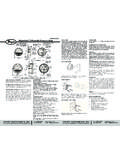
1 Proximity CONTROLSP hone: 219/879-8000 DIVISION OF DWYER INSTRUMENTS, INC. Fax: 219/872-9057e-mail: BOX 373 MICHIGAN CITY, INDIANA 46361, PSC/PSI Proximity SensorsSpecifications Installation and Operating InstructionsINTRODUCTION - Proximity SensorsThe Proximity Controls range of Proximity Sensors includes induc-tive and Capacitive Proximity switches and a Test unit. These arelisted and stocked in our catalog for fast service. Should you needa non-listed varient please contact the sales (PSI) switches will detect all metals.
2 Capacitive (PSC)switches will detect nearly all solids, powders and liquids. The A-800 Test Unit will give a functionality test to all versions stocked inthe catalog and will test most three wire DC Proximity switchesfrom other DISTANCES ensing ranges refer to a 1 mm thick square target of earthed mildsteel with sides of 3 x the nominal sensing distance. If the targetis a different material, or of another size, there will be a variationin the sensing (MECHANICAL)Flush MountingUnits designed for flush mounting, including all inductives listed inthe catalog, may be fitted in surrounding metal as MountingUnits designed for non-flush mounting, including Capacitiveswitches, must be separated from teh surrounding metal : Capacitive switches can, if required, be tuned down to befitted flush in metal.
3 See section on sensitivity (ELECTRICAL)Single UnitsDC units have transistor output, and normally have three wires,but NAMUR standard DC Sensors have only two Wire DC Switch2 Wire DC SensorNote that units with two wires must be connected to their powersupply with a load in Series , or they will be damaged. Consult cat-alog for load InterfaceProximity Sensors may be interfaced with most types of industriallogic. Most DC units are open collector type and therefore requirean external pull up resistor when used with TTl as that 3 wire DC-Compact V3 bodied switches are designed foruse directly with TTL and have a built-in pull up Units: ParallelDC Sensors may be connected directly in parallel as in shown.
4 Thenumber (N) of switches is usually only limited by the availability ofsufficient supply current. Note that the compact V bodied switcheshave an internal pull-up resistor with a resistance of 12 maximum number of compact switches in parallel is:N=Rating Load Current (mA) x 12 Kilohm / V SteelCast IronAluminum FoilStainless SteelBrassAluminumCopperWaterPVCG lassCeramicsWoodBeerCoca ColaLubricating FACTORSF lush FittingNon FlushFittingA= Not LessThan 3dBulletin E-81-PSE-81-PS:PS bulletin 2/4/10 8:05 AM Page 1 Multiple Units.
5 SeriesThe maximum number of DC Sensors connected in Series is limit-ed by the supply voltage (V supply), the voltage drop across aclosed switch (V switch) and either the minimum working voltageof the switch or minimum working voltage of the load, whichever isgreater (V min).The diagram above shows a typical Series configuration of PNPsensors. For NPN types, swap the blue for brown wire and ADJUSTMENTI nductive SwitchesInductive PSI Sensors are not SwitchesInstall the capacitive PSC sensor in its final position.
6 Remove theblack cover screw to gain access to the adjustment the adjusting potentiometer clockwise to increase sensitivityor counterclockwise to reduce sensitivity. For example, the rangeand sensitivity of capacitive Sensors can be adjusted to tune outthe sidewall of a plactic container or glass window of a signt glasssuch that the level of liquid, granules or powders on the other sideof the plastic or glass can be this application tune out the sight glass or wall with the con-tainer empty, detune the sensor so it cannot see the window orwall.
7 Then test the settings by introducing the target materialinside the container. Caution should be taken with materials thatleave a residue inside the container as this may be : To maintain the IP65 rating on capacitive Sensors , it isimperative that the black cover screw be replaced after INFORMATIONLED IndicatorsMost Proximity Sensors are fitted with indicator lights (LED s) atthe cable end. The LED indicates the state of the switch VoltageThe maximum voltage of DC Proximity Sensors is 30 V.
8 It is some-times forgotten that a rectified 24 VAC supply has a peak value X the AC RMS value (34V).NOTE: These switches should be installed by competent person-nel only. Please check wiring and supply voltages before switch-ing on. If there are any technical questions regarding installationor application of Proximity Sensors please contact the technicalsales DC Proximity Switch Test UnitThe A-800 is fitted with two PP3 batteries ready for use. This unitwill test most 3 wire DC Proximity switches PSI (metal sensing),PSC (most materials), the magnet sensing Detector (DT), photo-electrics or color coding for 3 wire Proximity switches isBrown=Positive (+), Black=Load, Blue=Negative ( ).
9 Note: Someuniversal DC switches can vary. Follow the maufacturer s InstructionsConnect the switch to the A-800. Place a suitable target in front ofthe switch. If it is functioning correctly, the test unit will give audioand visual indication showing that the switch operates and indicat-ing functionality of the switch according to the chart DC TEST UNITIf the Proximity switch does not give such feedback when correct-ly connected to the tester, it has probably failed. NOTE: The A-800will not test 2 wire AC or DC FunctionsGreen I/O LEDS witch connected and unit onRed (Battery) LEDB attery low indicatorPNP or NPN LEDI ndicated switch typeFurther Information: Proximity is a Division of Dwyer Instruments, Inc.
10 For further infor-mation, a copy of our latest catalog, other products or details con-cerning our nearest distributor please call our sales TYPEPNP & LED ON WHENT arget in rangeTarget not in rangeTarget in rangeTarget not in rangeE-81-PS:PS bulletin 2/4/10 8:05 AM Page 2 INSTALLATION AND WIRING INSTRUCTIONS INDUCTIVES CAPACITIVES TEST UNITINTRODUCTIONThe Proximity range includes inductive and Capacitive proximityswitches and a Test unit. These are listed and stocked in out cat-alog for fast service.