Transcription of Basic Analog Electronic Circuits Dr. Lynn Fuller
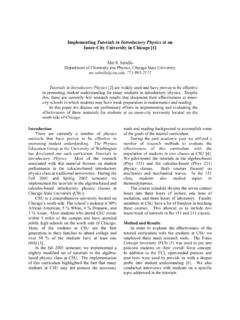
1 Page 111111111 Page 2 Page 3 Page 4 This is the CMOS op amp that we will build in lab. Look carefully at the schematic and identifythe current sources, reference current, differential amplifier, active loads, common source 2ndstage with active load and scope probe. (note: MEG works in spice but M is milliand m is also milli) Note the current source for the 2ndstage is different than M8 in that R3 will make the current 5 Start with the DC analysis. In LTSPICEthe .op command does the DC analysis and lists all the node voltages and branch currents in a table after running the simulation. Some of the results in the table are given here. The reference current I(R2) is mA and is matched with the current source IM8=IEE= IEE splits in half for the diff amp transistors giving mA each. The current in the 2ndstage is The DC output offset voltage is 40mV which is close to zero as 6 One way to get the voltage gain (the otheris to input sine wave) is to do a DC sweep near zero volts.
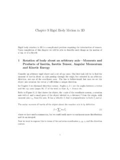
2 In this example we sweep from -40mV to +40mV is small steps. The output voltage is shown in green. The derivative of the green plot is shown in dark blue in the top plot plane and is the overall voltage gain. The derivative of the differential amp stage output voltage is the gain of the diff amp shown in the middle plot plane. The maximum overall gain is ~4000V/V and for the diff amp is ~60V/VPage 7 Similarresults are found for sinusoidal input. Page 8 This shows two versions ofthe layout of the op amp shown on the previous few pages. The upper design is based on L=2um. The lower design is a L=1um design. They should both work but the larger one always works when made by RIT 9 With a 10K load the voltage gain drops from ~4000V/V to ~600V/V. Obviously this amplifier haslittle ability to output current to loads less than 1 MEG 10 LTSPICE for CMOS op amp with output stage to drive loads of 100 11A few extra transistors allows the op amp to drive 100 ohm 12 Please 13 Page 14 More fromthe data 15 This is a plotof the voltage gain and phase vs Frequency for an inverting amplifier configuration with, Rfand Rin, to give a low frequency gain to 40 dB or 100 16 This is a low voltage op amp from LinearTechnology that can output up to 17 These properties imply in zero currentinto either of the differential inputs because the input resistance is very small voltage difference between the two inputs, (we say Vin+ and Vin-are at virtually the same voltage).
3 This is because if the output voltage is finite the input is output divided by the very high gain, resulting in a very small voltage difference 18 These Basic op amp circuitsshould be familiar. Lets apply ideal op amp fundamentals to the Inverting amplifier. Vin+ and Vin-are virtually at the same voltage, virtual ground and ground. The current in R1 is Vin/R1. With infinite input resistance the current in R1 has to go through R2 creating a voltage at Vo of I x R2 which is equal to Vo. Combining these two equations we have Vo/Vin = -R2/R1 the inverting amplifier gain. You can apply these same concepts to derive the output equations for each of these Circuits . Note the feedback connection always goes from Vo back to the inverting 19 Two more Basic opamp Circuits . You can use the concepts of the ideal op amp with other circuit analysis techniques to derive the equation for the output voltage.
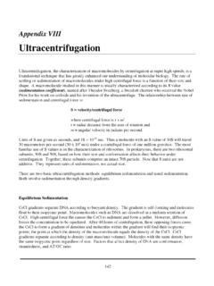
4 The concept of superposition for linear Circuits can help with these two Circuits . That is find Voutdue to V1with V2 equal to zero and add the result to Voutdue to V2 with V1 equal to 20 Most op amp Circuits usedual power supplies so that the input and output voltages are referenced to ground. However, it is sometimes useful to use a single supply instead of two. In the single supply case the input and outputs should be referenced to a voltage near of the single supply value. This requires careful consideration of grounds and Analog signal grounds which are not the same for single supply op amp Circuits . Page 21 This is an example of a single supply op amp inverting amplifier for a small DCinput voltage from a thermopile, Vin. If you had a Analog ground at a voltage at way between the +V and ground the output voltage would be way between +V and ground for no Vin. With Vin not zero Voutwill be Vin (R2/R1) plus V+/2 22 This shows a single supply amplifier for a sinusoidal input witha DC offset equal to the Analog ground.
5 In this case V+ divided by two. The output voltage is a sinusoid on a DC offset of V+/2. That is 5/2 = 23 Single resistors can be used to sense temperature, light, strainand are used in pressure sensors, accelerometers and other applications. With a dual supply op amp a small change in resistance can be converted to a change in voltage with a circuit such as the dual supply op amp circuit shown above. Initially R1 and R2 are identical and vin is zero. If the sensor resistor R1 increases in response to some physical change vin will decrease slightly. The amplifier has a gain of Gain = 1 + (R3/R4) withinfinite input resistance. Voutwill be a DC voltage relative to ground or zero 24 This is an example of the non linear operation of an op ampbecause there is no feedback from output to the inverting input. Because of the high gain of the op amp any small difference in Vin compared to Vrefwill be amplified by the huge gain of the op amp.
6 So the output will be either +V or V depending on if Vin is less than or greater than Vref. The voutvs vin plot is shown for Vin swept from V to +V. The Voutwill be +V when Vin is less than Vrefand V when Vin is greater than 25If the reference voltage Vrefcomes from Voutand a voltage divider R1/(R1+R2)then the reference voltage will have two different values one when Voutis high and a different value when Voutis low. If R1 is equal to R2 for example the reference voltage will be either +V/2 or V/2. This will create hysteresis in the Vo vs Vin plot depending on which direction the Vin is being swept. If Vin is swept from low to high, Voutwill start high, +V, (because the reference voltage is connected to the non-inverting input) and Voutwill switch to low V when the input gets to V/2. When sweeping in the negative direction the reference will be V/2 and switching Voutto high when Vin reaches 26 Instead of sweeping the input lets use a RC circuitto charge a capacitor to what ever the output voltage is at.
7 If the output voltage is high the capacitor will try to charge up to high. If the RC circuit is used with the comparator circuit discussed on the previous page the output voltage will switch to low when the capacitor voltage reaches Vrefmaking the output low and the capacitor will try to discharge to low but before I gets to V it reaches the VrefLow and the output switches to Thus continually oscillating high and low depending on the RC time 27 The voltage across the capacitor charges from Vreftowards +V with time constant RC at +Vrefit triggers and changes to charge toward V with time constant RCand continues to 28A changing input voltage will charge up the capacitor C tothe peak of Vin. The capacitor will slowly discharge backwards through the diode with a constant current equal to the reverse leakage current, Is. The equation shown can be used to calculate the change in voltage on a capacitor when it is being discharged with a constant current.
8 For example if Is=10nA and C=1uF the voltage across the capacitor can decrease at 10 millivolt per second. Adjusting the value of C changes how quickly Voutcan respond to changes in 29 Theequations at the top show the relationship for voltage and current in a capacitor. The equation in the box can be used to calculate the capacitance for two parallel plates. Other conductor configurations have different equations for 301616161616161616 This shows anapproach for an Analog circuit design that will indicate when a capacitor sensor has reached some value. For example a capacitor used to measure a liquid level and when full turn on an LED indicator. Each block in the design approach above is converted into a circuit schematic on the next 31 This shows the op amps andother components used to realize the capacitor sensor 32 The circuit design from the previous page was used with a capacitor force sensor.
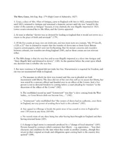
9 Two parallel plates with foam between the plates. Pressurecan push the plates closer increasing the capacitance. The buffer output shows that the waveform peak is related to the capacitance value. A bread board for this circuit was built and the signals were obtained using an oscilloscope. Note: this type of circuit can detect slowly changing capacitance values or even different steady capacitance 33 Microphones havea capacitor sensor that changes with sound pressures. The capacitor is a thin flexible diaphragm parallel plate structure. A small microphone, like the one in your smart phone, might have a capacitance of several pF with changes in capacitance of a few hundred fFin response to sound pressure waves. The capacitance changes will be at audio frequencies, say 1 KHz to 10 KHz range. The capacitance is shown as C0 + Cm sin (2pft) where Co might be 10pF and Cm might be 100fF and the frequency might be 5 KHz.
10 The calculation for Vo is shown in this slide. Do the math and find the amplitude of the output voltage for R of 1 MEG. This circuit converts changing capacitance to changing 34 Photo diodes output current that is proportional to light intensity. The voltage changesa little but not much, always around .5 to .7 volts. This circuit is a current to voltage converter not a voltage amplifier. Light will cause current to flow out of the p-side of the diode. That current flows through the feedback resistor creating the output voltage relative to ground, virtual ground. Page 35 Lightintensity changes many orders of magnitude from dark to very bright. A non linear current to voltage converter is shown here where the feedback resistor is replaced with a diode. The plot shows the difference between a linear amplifier, R in feedback, and logarithmic amplifier, diode in feedback, for photo diode currents over many orders of magnitude.