Transcription of ET Series Stepper and Servo Driven Linear Actuators
1 Rotary Actuators and Bulletin PM-ET01/USA. Automation Maintenance Instructions &. Parts List Effective: January 1, 1998. ET Series Stepper and Servo Driven Linear Actuators PM-ET01/USA Stepper and Servo Driven Linear Actuators ET Series Who's Who ER Series Rodless Actuators Voice (330)336-3511 - Fax (330)334-3335. Tim Armstrong Ext. 248 Order Entry & Expediting Technical information TBA Ext. 228 Applications, Spare Parts Erin Weitzel Ext. 289 Programming Chris Griffin Ext. 277 Electro-Mechanical Product Sales Manager Greg Haitz Ext. 229 Marketing Manager Jeff Cullman Ext. 222 General Manager WARNING. FAILURE OR IMPROPER SELECTION OR IMPROPER USE OF THE PRODUCTS AND/OR SYSTEMS DESCRIBED HEREIN OR. RELATED ITEMS CAN CAUSE DEATH, PERSONAL INJURY AND PROPERTY DAMAGE. This document and other information from Parker Hannifin Corporation, its subsidiaries and authorized distributors provide product and/or system options for further investigation by users having technical expertise.
2 It is important that you analyze all aspects of your application and review the information concerning the product or system in the current product catalog. Due to the variety of operating conditions and applications for these products or systems, the user, through its own analysis and testing, is solely responsible for making the final selection of the products and systems and assuring that all performance, safety and warning requirements of the application are met. The products described herein, including without limitation, product features, specifications, designs, availability and pricing, are subject to change by Parker Hannifin Corporation and its subsidiaries at any time without notice. Offer of Sale The items described in this document are hereby offered for sale by Parker Hannifin Corporation, its subsidiaries or its authorized distributors. This offer and its acceptance are governed by the provisions stated on the separate page of this document entitled "Offer of Sale".
3 Copyright 1997, Parker Hannifin Corporation, All Rights Reserved 2 Parker Hannifin Corporation Automation actuator Division Automation Wadsworth, Ohio PM-ET01/USA Stepper and Servo Driven Linear Actuators Table of Contents ET Series Description Page No. Product information .. 4. Features .. 5. Ordering 6, 7. Exploded View .. 8. Parts List .. 9 - 13. Maintenance/Torque Table, Cleaning .. 14. Maintenance/Adjusting Timing Belt Tension .. 15. Lubricants, Motor Coupler and Pulley Spacing .. 16. Assembly information .. 17. Pinouts - Servo Systems .. 18 - 21. Pinouts - Stepper Systems .. 21 - 23. Stepper Motor Options .. 24, 25. Hall Effect Sensors .. 26. Reed Switch 27. Reed Switch 28. Quick Connect and Brake Option .. 29. 3 Parker Hannifin Corporation Automation actuator Division Automation Wadsworth, OH 44281. PM-ET01/USA Stepper and Servo Driven Linear Actuators Product information ET Series ET Series Stepper and Servo Driven Linear Actuators Maintenance Instruction & Parts List Electric Cylinder features: This publication provides maintenance instructions, replacement parts information , options information , and system connec- tion tables for the ET Series .
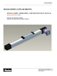
4 The ET Series Linear actuator offers robust, modular design and easy integration in a packaged electric cylinder. Available in four ISO mounting profile sizes, the ET Series can produce thrusts to 5300 lb and Linear speeds to 60 inches per second. Combined with a Parker Hannifin Stepper or Servo system, the ET Series becomes a fully programmable Linear actuator system. ET Series Features Produced to hard metric ISO standards Four ISO mount sizes: 32mm, 50mm, 80mm, 100mm Angular contact thrust bearings at rear of screw Long length rod bearing Extruded, anodized aluminum body with integral switch/sensor grooves Unique anti-rotate nut bearing carriage Polyurethane bumper at ends of travel Low-friction ball bearing nut and quality rolled ball screw option Low-friction burnished lead screw with bronze nut option Ground and polished stainless steel rod Integral sensing magnet High quality flexible couplings High performance Stepper and Servo motors Motor Systems Microstepping systems DC Brushless Servo systems with encoder or resolver feedback User provided AC or DC motor systems Control Systems Microprocessor-based programmable single and multi-axis Stepper and Servo controllers User-friendly 6000 and X languages from Compumotor 4 Parker Hannifin Corporation Automation actuator Division Automation Wadsworth.
5 Ohio PM-ET01/USA Stepper and Servo Driven Linear Actuators Features ET Series Main Components Diagram The figure below represents the main components of an ET Series Linear actuator . Reverse parallel mounting shown for convenience. Reverse-parallel cylinder Parallel timing belt housing *. Front end cap Anti-rotate hearing carriage * Parallel cylinders only 5 Parker Hannifin Corporation Automation actuator Division Automation Wadsworth, OH 44281. PM-ET01/USA Stepper and Servo Driven Linear Actuators Ordering information ET Series MODEL CODE AND ORDERING information . Example: ETS50-B05PA21-FMAE600L-A ETS 50 B05 P A 2 1. Catalog Feature Description Symbol Page Series Electro-Thrust Stepper Series C1 ETS. Electro-Thrust Brushless Servo Series B1 ETB. Model/Size 32 mm - 32. 50 mm - 50. 80 mm - 80. 100 mm - 100. Drive Ball Screw, in ( mm) lead, Size 100 See Curves B53. Screw Type Ball Screw, in ( mm) lead, Size 50 & 80 See Curves B01. Ball Screw, .500 in ( mm) lead, Size 32, 50, 80, 100 See Curves B02.
6 Ball Screw, .250 in ( mm) lead, Size 80, 100 See Curves B04. Ball Screw, .200 in ( mm) lead, Size 50 See Curves B05. Ball Screw, .125 in ( mm) lead, Size 32 See Curves B08. Acme Screw, .250 in ( mm) lead, Size 32, 80, 100 See Curves A04. Acme Screw, .200 in ( mm) lead, Size 50 See Curves A05. Acme Screw, .125 in ( mm) lead, Size 32 See Curves A08. Motor Inline, Direct Drive, Motor on End D2 L. Mounting Parallel Version, Timing Belt, Motor Position (1) D2 P1. Style Parallel, Timing Belt, Motor Position (2) D2 M. Parallel, Timing Belt, Motor Position (3) D2 N. Parallel, Timing Belt, Motor Position (4) D2 Q. Reverse Parallel, Timing Belt, Motor Position (1) D2 R. Reverse Parallel, Timing Belt, Motor Position (2) D2 S. Reverse Parallel, Timing Belt, Motor Position (3) D2 T. Reverse Parallel, Timing Belt, Motor Position (4) D2 V. Drive Ratio Inline Direct or Parallel, Ratio 1:1 See Curves A. Parallel, Ratio :1 See Curves B2. Parallel, Ratio 2:1 See Curves D2.
7 Parallel, Ratio 1 , Available on ET32 only See Curves Z. ETS. Stepper NEMA 23, Size 32 and 50 C62-63 2. Motor Nom- NEMA 34, Size 50 and 80 C62-63 3. inal Mounting NEMA 42, Size 80 only C62-63 4. ETB. Size Special - 9. Stepper No Motor, Flange and Coupling only - 0. ETS. Motor Style Std. Motor, Cable Grommet, w/o Damper C55 1. Std. Motor, Conduit Connection, w/o Damper C56 2. Std. Motor, Brad Harrison Connector, w/o Damper C57 3 ETB. Std. Motor, Cable Grommet, w/ Damper C58 4. Std. Motor, Conduit Connection, w/ Damper C58 5. Std. Motor, Brad Harrison Connector, w/ Damper C58 6. Special Motor* - 9. 1 Brushless NEMA 23, Flange & Coupling/Pulley only B48-49 2 0. Will obstruct standard (12 o'clock) switch groove orientation. Servo NEMA 34, Flange & Coupling/Pulley only B48-49 3 0. Motor SM233BE-LTQN, Size 32 & 50 B48-49 2 2. Not available on ET32 or ET100. Not Options3 SM233BR-LMSN, Size 32 & 50 B48-49 2 3. available with larger frame size motor on (ETB APEX 60X Flange & Coupling/Pulley only, Size 50 & 80 B50-51 6 0.)
8 ET50 and ET80. See chart on facing page. Series ) APEX 605 Motor, Size 50 & 80 B50-51 6 1. APEX motors purchased through AAD. APEX 606 Motor, Size 50 (inline only) & 80 B50-51 6 2. includes (25 ft.) motor and resolver cable. SM233BE-LTQN option includes APEX 610 Motor, Size 80 B50-51 6 3. 23TQ Cable-10. SM233BR-LMSN option APEX 620 Flange & Coupling/Pulley only, Size 100 B50-51 7 0. includes 23RS Cable-10. APEX 620, Size 80 (inline only) & 100 B50-51 7 1. * Special motore/reducers must be mounted APEX 640, Flange & Coupling/Pulley only, Size 100 B50-51 8 0. at factory. APEX 640, Size 100 B50-51 8 1. Special, Flange & Coupling/Pulley only* - 9 0. 6 Parker Hannifin Corporation Automation actuator Division Automation Wadsworth, Ohio PM-ET01/USA Stepper and Servo Driven Linear Actuators Ordering information ET Series F M A E 600 L A. Catalog Feature Symbol Description Page A - Assigned by Factory Design Series Omit - No Linear Potentiometer Linear L - Linear Potentiometer Potentiometer 50 - ET32, ET50, ( ) Stroke Length 100 - ET32, ET50, ET80, ET100 ( in) (in mm).
9 150 - ET32, ET50,ET80, ET100 ( in). 200 - ET32, ET50, ET80, ET100 ( in). 300 - ET32, ET50, ET80, ET100 ( ). 450 - ET32, ET50, ET80, ET100 ( in). 600 - ET32, ET50, ET80, ET100 ( in). 750 - ET32, ET50, ET80, ET100 ( in). 1000 - ET50, ET80, ET100 ( in). 1250 - ET80, ET100 ( in). 1500 - ET80, ET100 ( in). 7. Omit - No Brake Brake Option E E4 115 VAC w/ Fling leads and cable gland on lead screw F E4 24 VDC w/ Flying leads and cable gland on lead screw G E4 115 VAC w/ Brad Harrison conn. & 4m cable H E4 24 VDC w/ Brad Harrison conn. & 4m cable V - 115 VAC w/ Flying leads and cable gland on Stepper W - 124 VDC w/ Flying leads and cable gland on Stepper Y - 115 VAC w/ Brad Harrison conn. & 4m cable on Stepper Z - 24 VDC w/ Brad Harrison conn. & 4m cable on Stepper Omit - Standard (12 o'clock) Body A - 3 o'clock Orientation 6. B - 6 o'clock C - 9 o'clock M D12 Male (Metric Standard) Rod End F D12 Female K D12 Male - Imperial C D13 Clevis S D13 Spherical Rod Eye R5 D15-20 Linear Rod Guide Module X - Special B4 D3 Foot Mount (MS1) Cylinder C4 D10 Rear Clevis (MP2-R) Mounting D D4-5 Trunnion (MT4).
10 E4 D9 Rear Eye (MP4). F B48-49 Bottom Tap (MS4) (Standard). G D8 Foot Side Lug H4 D7 Rear Flange (MF2). J D6 Front Flange (MF1). 4 N4 D7 Front & Rear Flange (MF1 & MF2). Not available with Inline (L). Motor Mounting. X - Special 5. Linear rod guide module may interfere with some switch groove orientations (Body Orientation A and C) on ET32, ET50 & ET80. Not compatible with G, J, or N mounting options. 6. Switch Groove Orientation as viewed from Cylinder Shaft End. May decrease side load capacity. ET100 has switch grooves on all four sides. 7. Not available on ET32 or NEMA 23 motors. Options (E,F,G & H) not compatible with rear mounting options (B,C,E,H & N). Options (V,W,Y & Z) not compatible damper or encoder. Available Drive Ratio Combinations (Parallel only) (ET100 1:1 only). Size S57-102 S83-135 S106-178 SM233B APEX605 APEX606 APEX610. 32 1:1, 1 - - 1:1, 1 - - - 50 1:1, :1, 2:1 1:1, :1 - 1:1, :1 1:1 - - 80 - 1:1, :1, 2:1 1:1, :1 - 1:1, :1 1:1, :1 1:1, :1.