Transcription of Linear Motors Complement Today’s Linear Motion …
1 Parker Hannifin Corporation Jack Barrett Tim Harned Jim Monnich Linear Motors Complement Today s Linear Motion Technologies. Today s Linear Motion applications are more demanding than ever before. Faster throughput, more exact positioning, longer life, less maintenance, fewer moving parts, the list is never ending. Motion control companies strive to meet and exceed these requirements by continual technological advancement. Less than a decade ago, it was a difficult task to find a commercially available Linear bearing that could travel 5 meters per second with straightness, load capacity and stiffness. Today there are many Linear bearings with these attributes and they are fairly cost effective. Advancements in Linear encoder technology allow higher speed operation too. Today s Linear encoders and other devices are able to meet this challenge, are less noise susceptible, and cost less.
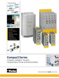
2 So with two of the three primary Linear Motion elements rising to the high speed, high accuracy challenge, the limiting factor is the drive drain. Left, Photo of today s high precision high speed Linear Motion technologies: Linear Guide bearings with Speeds to 5 meters per second and load capacity of thousands of pounds. Non-contact Linear encoders with sub micron resolution and speeds to 3 meters per second. Improvements in Linear , mechanical drives have also moved forward. Ball screw s with higher accuracy, and faster lead's result in higher throughput. Timing belts have high repeatability and speeds of well over 5 meters per second. Both of these technologies have historically solved Motion control applications, and will continue to do so. However, neither of these provide the speed and accuracy combination required by an increasing number of today s Motion applications More and more we face the HIGH ACCURACY, HIGH SPEED APPLICATION.
3 To solve this, the drive train must be able to respond faster, have less wear and have extremely high resolution capabilities. A device that can provide this does exist! It is the Brushless Linear motor . The Linear motor Concept: The idea is simple enough. Take a conventional rotary servo motor and unwrap it. So now what was the stator is now a forcer and the rotor becomes a coil or magnet rail. With this design, the load is connected directly to the motor . Direct Linear Motion is achieved without any rotary to Linear transmission devices. Linear motor technology is not new. Step motor and brushed Linear motor products have been available for quite some time. Brushless technology is becoming increasingly popular as applications take advantage of its technology. Brushed Linear had the coils in the Linear rail and the magnets were in the forcer. Commutation was accomplished by a Linear commutation bar that ran the length of the motor with brushes in the forcer.
4 This method was both expensive and limited. The cost of winding feet after feet of Linear motor rail was time and material intensive. High speed operation was limited due to commutation bar and brushes. Linear step Motors have both windings and permanent magnets within the forcer. It travels along a rail having an etched tooth structure. While maintaining the step motor advantage of open loop operation, the technology does have some limitation in speed and available force. With brushless servo motor technology, and the supporting electronics to drive them, the above limitations have been eliminated. The forcer is now a set of windings while the stator is a rail of magnets. Commutation is done electronically either by Hall-effect sensors or sinusoidal. Hall effect sensors located within the forcer are activated by the magnets on the rail. The amplifier translates these signals into appropriate phase currents.
5 Sine commutation is accomplished using the Linear encoder signals back to the controller. A common technique is the use of Hall-effect initially and then switching to sinusoidal commutation. In any case, the speed of commutation is not the limiting factor. The force generated by the same size motor is greater than brush motor technology due to improved magnet materials. Linear motor Benefits: High speeds, The maximum speed of a Linear motor is limited only by the bus voltage and the speed of the control electronics. Typical speeds for Linear Motors are 3 meters per second with 1 micron resolution and over 5 meters per second, 200ips, with coarser resolution. High Precision: The accuracy, resolution, and repeatability of a Linear motor driven device is controlled by the feed back device. With the wide range of Linear feedback devices available, resolution and accuracy are primarily limited to budget and control system bandwidth.
6 Fast Response: The response rate of a Linear motor driven device can be over 100 times that of a mechanical transmission. This means faster accelerations and settling times, thus more throughput. Stiffness: Because there is no mechanical linkage, increasing the stiffness is simply a matter of gain and current. The spring rate of a Linear motor driven system can be many times that of a ball screw driven device. However it must be noted that this is limited by the Motors peak force, the current available and the resolution of the feedback. Zero Backlash: Without mechanical transmission components, there is no backlash. Resolution considerations do exist. That is the Linear motor must be displaced by 1 feedback count before it will begin to correct its position. Maintenance Free Operation: Because the Linear Motors of today have no contacting parts there is no wear. What are the Down Sides?
7 Cost: Linear Motors are expensive. This is due to the relative low volume produced, and the price of magnets. Since most Linear motor designs mount rare earth magnets to the length of the rail, and the cost of these magnets is high, long travel Motors become expensive. However as the popularity of Linear Motors continues, volume will rise and cost will decline. This process has begun. Linear feedback must also be considered in the cost of using a Linear motor . Rotary motor feedback, (encoder or resolver) is relatively inexpensive (<$100 list) and is not length dependent. Linear Motors typically require a Linear encoder for feedback. These devices are many times more expensive than their rotary counterparts. A 100 mm travel Linear encoder list in the neighborhood of $500, and cost increases with length. With newer reflective type encoder technologies, the manufacturing costs are declining, and with continued increases in the use of these encoders, prices will follow.
8 Most importantly, if system accuracy requires Linear encoder feedback, the cost differential between Linear and rotary technology is greatly reduced. Higher Bandwidth Drives and Controls: Since there is no mechanical reduction between the motor and the load, servo response, bandwidth, must be faster. This includes higher encoder bandwidth and servo update rates. Force Per Package Size: Linear Motors are not compact force generators compared to a rotary motor with a transmission offering mechanical advantage. For example to produce even 65 N (15 lb) of continuous force, a Linear motor s cross section is approximately 50 mm x 40 mm (2 x ). Compare this to the cross section of a 10 mm (3/8 ) diameter ball screw which produces 100 lb. of thrust and one can see that Linear Motors are not brute force devices. Heating: In most Linear motor applications, the forcer is attached to the load.
9 Any I2R losses are then directly coupled to the load. If an application is sensitive to heat, thermal management techniques need to be applied. Air and water cooling options are popular and common. No (minimal) Friction: This may not sound like a problem, but it certainly can be. For instance, a Linear motor is traveling at 3 meters/second (120 ips) and loses power. Without some resistance in the system, it does not take long before the motor reaches the end of stroke and mechanical stops. Choosing a Linear motor : Choosing the right Linear motor for an application is not a simple task. Selecting the right technology for the application, force calculations, thermal considerations, bearing loading, commutation methods, etc., must be considered. Within this article, technology will be discussed, not sizing solutions. However, knowing the basic types and the associated advantages and disadvantages will assist in the end solution.
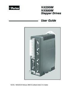
10 Three technologies of brushless Motors are discussed. They are; ironcore, aircore (ironless), and slotless. IronCore Linear motor Construction: This motor takes its design straight from a brushless rotary motor . As shown in , the motor consists of a flat iron rail to which rare earth permanent magnets are bonded. The Forcer is constructed of laminations and coil s wound around the teeth of the laminations. Thermal sensors are mounted internal to the windings, sensing temperature. Hall effect sensors are either mounted in the coil area or mounted on the edge of the motor . These sensors are activated by the magnets on the rail and used for commutation of the windings. Advantages: Highest Force per Size: Utilizing laminations to concentrate the flux field, this type of motor produces the greatest force per package size. Lower Cost / Lower Weight Rail: The next type of motor we will examine is the AirCore motor .