Transcription of Power supplies - Learn About Electronics
1 module 3 Switched Mode Power supplies 1 module Introduction to Switched Mode Power supplies . SMPS circuits are considerably more complex than the linear stabilised Power supplies described in Power supplies module 2. The main advantage of this added complexity is that switched mode operation gives stabilised designs that can deliver more Power for a given size, cost and weight of Power unit. A number of different design types or topologies are used. Where the input is the AC mains (line) supply the AC is rectified and smoothed by a reservoir capacitor before being processed by what is in effect a DC to DC converter, to produce a regulated DC output at the required level.
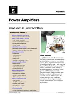
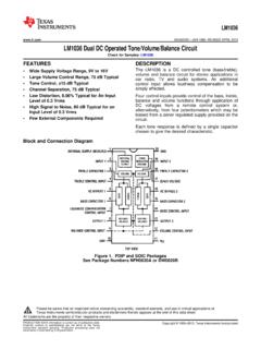
2 Hence a SMPS can be used to convert AC to DC, such as in a desktop computer Power supply, or DC to DC, either step up or step down in many different battery powered systems. Fig. shows a block diagram example of a typical SMPS with an AC Mains (line) input and a regulated DC output. The output rectification and filter are isolated from the High Frequency switching section by a high frequency transformer, and voltage control feedback is via an opto isolator. The control section is typical of specialist ICs containing HF oscillator, pulse width modulation, voltage and current control and output shut down sections.
3 Whatever the purpose of a SMPS, a common feature (after conversion of AC to DC if required) is the use of a high frequency square wave to drive an electronic Power switching circuit. This circuit switches the direction of the supply current in the primary winding of a transformer at typically 20kHz to 100kHz. A high frequency, high current AC is therefore produced in the transformer secondary. This may be rectified and smoothed in a number of ways to produce a stabilised DC supply of either a higher or lower level than the input voltage, depending on the topology used. By using an oscillator and switch in this way to convert DC into AC, the switched mode technique can also be used as an inverter to create an AC supply at mains potential from a DC battery supply.
4 In most switched mode supplies , regulation of both line (input voltage) and load (output voltage) is normally provided. This is achieved by altering the mark to space ratio of the oscillator waveform before applying it to the switches. Control of the mark to space ratio is achieved by comparing voltage feedback from the output of the supply with a stable reference voltage. Both over voltage and over current may also be provided. Typical SMPS Block Diagram module 3 Switched Mode Power supplies 2 Where it is important to maintain electrical isolation from the mains supply, this is provided by using a transformer, either at the AC input where it may also be used to alter the AC voltage prior to rectification, or between the control section of the Power supply and the output section where, as well as providing isolation, a transformer with multiple secondary windings can produce several different voltage outputs.
5 To provide efficient regulation, a sample of the DC output voltage is normally fed back to the control circuitry and compared with a stable reference voltage. Any error produced is used to control the output voltage. To maintain electrical isolation between input and output, feedback will usually be via a device such as an opto-isolator. Using high frequency for the switching drive gives several advantages: The transformer will be of a HF type, which is much smaller than a standard mains transformer. The ripple frequency will be much higher ( 100kHz) than in a linear supply, and so it needs a smaller value of smoothing capacitor.
6 Also using a square wave to drive the switching transistors (switched mode operation) ensures that they dissipate much less Power than a conventional series regulator transistor. Again this means that smaller and cheaper transistors can be used, than in similarly rated linear Power supplies . The use of smaller transformers and smoothing capacitors makes switched mode Power supplies lighter and less bulky. The added cost of the complex control circuitry is also offset by the smaller, and therefore cheaper transformers and smoothing capacitors, making some switched mode designs less expensive than equivalent linear supplies .
7 Although linear supplies can provide better regulation and better ripple rejection at low Power levels than switched mode supplies , the above advantages make the SMPS the most common choice for Power supply units in any equipment where a stabilised supply is needed to deliver medium to large amounts of Power . A disadvantage of using such a high frequency square wave in a powerful circuit such as a SMPS is that many high Power harmonics are created, so that without very effective RF screening and filtering, there is a danger of the SMPS creating RF interference. module 3 Switched Mode Power supplies 3 module The Buck Converter The Buck Converter uses the energy stored in the inductor L, during the on periods of the switching transistor output to supply the load during the off periods.
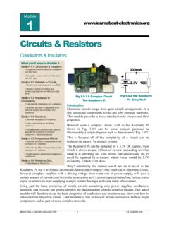
8 The circuit operation depends on what is also sometimes called a Flywheel Circuit. This is because the circuit acts rather like a mechanical flywheel that, given regularly spaced pulses of energy keeps spinning smoothly (outputting energy) at a regular rate. The buck converter is a form of DC to DC converter, which can take a DC input directly from a DC source, such as a battery, or as shown in Fig. from the rectifier/reservoir capacitor circuit. This DC is then converted to AC, using a switching or chopper transistor, driven by a (usually pulse width modulated) high frequency square wave.
9 This square wave is then re-converted to DC. Variations of this basic circuit can be used to take an AC input at high voltage directly from the mains (line) supply, or at a lower voltage via a step down transformer. Buck Converter Operation As shown in Fig. the buck Converter circuit consists of the switching transistor, together with the flywheel circuit (Dl, L1 and C1). While the transistor is on, current is flowing through the load via the inductor L1. The action of any inductor opposes changes in current flow and also acts as a store of energy. In this case the switching transistor output is prevented from increasing immediately to its peak value as the inductor stores energy taken from the increasing output; this stored energy is later released back into the circuit as a back as current from the switching transistor is rapidly switched off.
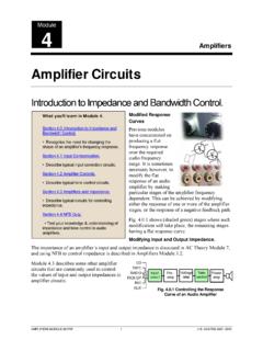
10 In Fig. therefore, when the transistor Tr1, is switched on it is supplying the load with current. Initially current flow to the load is restricted as energy is also being stored in L1, therefore the current in the load and the charge on C1 builds up gradually during the on period. Notice that throughout the on period, there will be a large positive voltage on D1 cathode and so the diode will be reverse biased and therefore play no part in the action. When the transistor switches off as shown in Fig the energy stored in the magnetic field around L1 is released back into the circuit.