High Efficiency Controller For Boost Sepic
Found 6 free book(s)
LT3757/LT3757A (Rev. G) - Analog Devices
www.analog.comHigh Efficiency Boost Converter FEATURES APPLICATIONS n Automotive and Industrial Boost, Flyback, SEPIC and Inverting Converters n Telecom Power Supplies n Portable Electronic Equipment Efficiency SENSE LT3757 VIN VIN 8V TO 16V 10µF 25V X5R VOUT 24V 2A 0.01˜ 41.2k 300kHz GATE FBX GND INTVCC SHDN/UVLO SYNC RT SS VC 200k 43.2k 0.1µF 22k …

AN-1484Designing A SEPIC Converter - Texas Instruments
www.ti.comSchottky diodes are recommended in order to minimize the efficiency loss. 4 AN-1484Designing A SEPIC Converter SNVA168E– May 2006– Revised April 2013 ... Similar to a boost converter, the SEPIC has an inductor at the input. ... Input voltage (VIN): 3.0 V-5.7V LM3478 controller is used in this example. The schematic is shown in Figure 5 ...
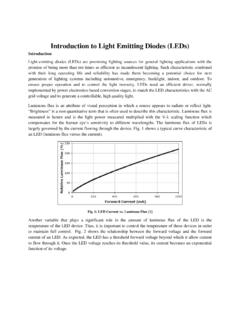
Introduction to Light Emitting Diodes (LEDs)
engineering.purdue.eduHence because of high efficiency and better illuminating quality, the PWM ... boost, and buck-boost in Fig. 6(a) to (c) and an isolated dc-dc converter in Fig. 6(d). The output voltage of the converters of Fig. 6 is ... The SEPIC converter is also one of the potential dc-dc converters for LED lighting. Fig. 7 shows the

CS5171 - Boost Regulators, 1.5 A, 280 kHz/560 kHz
www.onsemi.comregulators with a high efficiency, 1.5 A integrated switch. These parts operate over a wide input voltage range, from 2.7 V to 30 V. The flexibility of the design allows the chips to operate in most power supply configurations, including boost, flyback, forward, inverting, and SEPIC. The ICs utilize current mode architecture, which allows
Designing DC/DC converters based on ZETA topology
www.ti.comUnlike the SEPIC converter, which is configured with a standard boost converter, the ZETA converter is config-ured from a buck controller that drives a high-side L1aPMOS FET. The ZETA converter is another option for regulating an unregulated input-power supply, like a low-cost wall wart. To minimize board space, a coupled inductor can be used.
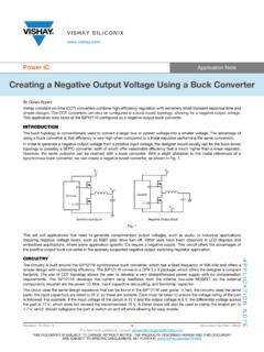
Creating a Negative Output Voltage Using a Buck Converter
www.vishay.comtopology or possibly a SEPIC converter, both of which offer reasonable efficiency that is much higher than a linear regulator. However, the same outcome can be reached with a buck converter. With a slight alteration to the nodal references of a synchronous buck converter, we can create a negative boost converter, as shown in Fig. 1. Fig. 1