Resonant Converter
Found 9 free book(s)
Ch4. LLC Resonant Converter - Virginia Tech
vtechworks.lib.vt.eduResonant converter, which were been investigated intensively in the 80's [B1]-[B7], can achieve very low switching loss thus enable resonant topologies to operate at high switching frequency. In resonant topologies, Series Resonant Converter (SRC), Parallel Resonant Converter (PRC) and Series Parallel
Design Considerations for an LLC Resonant Converter
www.resonant-converters.euResonant converter: processes power in a sinusoidal manner and the switching devices are softly commutated 9Voltage across the switch drops to zero before switch turns on (ZVS) • Remove overlap area between V and I when turning on • Capacitive loss is eliminated Series resonant converter / Parallel resonant converter
A Mathematical Guideline for Designing an AC-DC LLC ...
gansystems.comA. LLC Resonant Converter Voltage Gain Review The half-bridge LLC resonant converter prototype is shown in Fig. 1. The operating frequency range of the LLC PFC is defined as fp ≤ fs ≤ fr, where below-resonance operation is preferred to ensure the inductive impedance characteristics of the LLC resonant tank, so that the soft
NCP4318 - Advanced Synchronous Rectifier Controller for ...
www.onsemi.comResonant Converter NCP4318 NCP4318 is an advanced synchronous rectification (SR) controller for LLC resonant converter with minimum external components. It has two gate drivers for driving the SR MOSFETs rectifying the outputs of the secondary transformer windings. The two gate drivers have their own drain and source sensing pins and operate
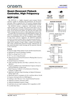
NCP1342 - Quasi-Resonant Flyback Controller, High Frequency
www.onsemi.comQuasi-Resonant Flyback Controller, High Frequency NCP1342 The NCP1342 is a highly integrated quasi−resonant flyback controller suitable for designing high−performance off−line power converters. With an integrated active X2 capacitor discharge feature, the NCP1342 can enable no−load power consumption below 30 mW.

USB Power Delivery and Type-C - STMicroelectronics
www.st.comconverter thanks to several power management & housekeeping functions. SO16N. L6699. High power adapters 90W to 250W. Datasheet : available on www.st.com. Series-resonant half -bridge topology • Self adjusting adaptive dead time • Anti-capacitive mode protection • Two-level OCP • Frequency shift • Immediate shutdown
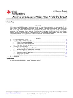
Analysis and Design of Input Filter for DC-DC Circuit
www.ti.comIf LC filter is not well damped, the frequency response will peak near resonant frequency, which means the LC actually is amplifying the noise signal. Apart from the amplification, sometimes, LC filter design also has effect on the control loop of the DC-DC converter, some poor LC filter will decrease the phase
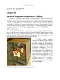
Variable Frequency Oscillators (VFOs) - QRP ARCI
www.qrparci.orgsustains the oscillation. The basic LC resonant circuit that determines the frequency is C1 and L1. C2 is a trimmer capacitor to help adjust the desired tuning range. So what are the values of C1, L1, C2, etc.? The answer isn’t simple. We start with a quality variable capacitor for C1 as described below. For various reasons, C1 will probably be

SIX MAIN COMPONENTS OF MRI SYSTEM
www.aheconline.comresonant frequency. MRI Core 12 PULSE SEQUENCE CONTROLLER The pulse sequence controller is responsible for the timing and performance of each system component. The pulse sequence controller dictates when and how much gradient power is needed to vary the magnetic field and spatially encode the MR signal.