Transcription of A Mathematical Guideline for Designing an AC-DC LLC ...
1 A Mathematical Guideline for Designing an AC-DC LLC converter with PFC Yajie Qiu1, 2, Member, IEEE; Wenbo Liu1, Student Member, IEEE; Peng Fang1, Member, IEEE; Yan-Fei Liu1, Fellow, IEEE; Paresh C. Sen1, Life Fellow, IEEE 1. Department of Electrical and Computer Engineering Queen s University, Kingston, Canada 2. GaN Systems Inc Ottawa, Canada Abstract Although LLC topology has been applied to AC-DC power supplies as a Power Factor Correction (PFC) converter in the literature, there is no publications present intuitive equations that simplify LLC Designing in order to meet the PFC gain requirements. In this paper, a Mathematical design Guideline is derived for LLC PFC converter applications, proving that by carefully Designing the resonant tank gain at parallel resonant frequency at the peak AC voltage higher than 1, its gain will meet the PFC requirement for other AC voltages and result in a successful single-stage PFC design with power factor over The Guideline is extended to offline wide input and output voltage LLC PFC applications.
2 A 240-Watt prototype of a single-stage LLC LED driver with PFC has been built to verify the feasibility of the proposed design Guideline . Keywords AC-DC converter ; PFC; LLC; Single-Stage; resonant converter I. INTRODUCTION Massive research have been attracted and new topologies have been studied on AC-DC power supply and its control strategy [1-6], LLC topology is still popularly used as the second stage converter to provide galvanic isolation and output voltage/current regulation [3, 4]. However, all the power is processed twice, which severely sacrifices the total efficiency and power density. To overcome this disadvantage, single-stage resonant solutions with PFC were discussed in [7-10]. The LLC resonant topology has been applied to a PFC converter in [7, 8] and then extended to an LED driver application in [9], resulting in power supplies with higher efficiency and a reduced profile.
3 However, the primary switches operate at an asymmetrical duty ratio in the this article, which not only results in control and driving circuit complexity, but also introduces third harmonics into the input current, sacrificing the optimal power factor performance. In [10], using the rectifier-compensated fundamental-mode approximation method, the feasibility of the LLC topology working as a PFC converter is proven with 50% duty cycle switch operation. However, there is still no intuitive Mathematical design Guideline to help engineers quickly design the LLC converter to achieve the power factor correction without over- Designing the gain. In this paper, a peak-gain-based Mathematical model is proposed for an LLC converter that will achieve power factor correction and also guarantee enough gain for the entire line voltage range.
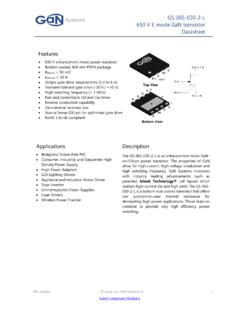
4 II. LLC resonant converter DESIGN Guideline FOR PFC A. LLC resonant converter Voltage Gain Review The half-bridge LLC resonant converter prototype is shown in Fig. 1. The operating frequency range of the LLC PFC is defined as fp fs fr, where below-resonance operation is preferred to ensure the inductive impedance characteristics of the LLC resonant tank, so that the soft switching can be achieved in both primary side switches and secondary diodes. SLSHLrCrLmn:1D2D1 CoIoVoRL+_ACviniin+- Fig. 1. Prototype of Half-Bridge LLC Power Factor Correction Circuit The maximum switching frequency is set at the series resonant frequency fr, expressed in (1). The quality factor Q, the inductance ratio K, the normalized switching frequency fn and the total gain of the converter MLLC_total are expressed in (2) to (5) [11-13] and n is the transformer s turns ratio.
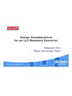
5 12rrrfLC = (1) 2222188outrrroutroutILLQnCV nCR = = (2) mrLKL= (3) rnsfff= (4) _22211211111 LLC totalnnnMnfQKff= + + (5) B. Single-Stage PFC Gain Requirement Analysis Fig. 2 plots the required voltage gain, Greq( ), for an LLC converter in PFC mode, according to (6). It is observed that Greq( ) to achieve power factor correction is different at each time instant, while the LLC converter output power pout( ) is also changing as per (7). Assuming the AC input voltage is 120 VRMS: at 90 , the LLC should provide two times the steady state output power (Ppk =2Po). At this time, the vin is at peak Vin_pk=120V , which is good for providing higher output power. At 45 , the LLC should provide the output power (Po), but vin is 120V sin(45 ) =120V.
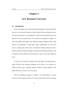
6 The LLC converter should generate Vo at 120V input at output power level of Po. At 30 , the vin = , and iin = , the output power is = Therefore, the LLC converter should provide Vo at the output power level of In order to achieve high power factor correction performance, the LLC converter must achieve different gains at different input voltages. For PFC application, the output voltage is usually a constant. When Pout decreases, Rout also linearly increases. Fig. 3 plots the normalized LLC tank gain at parallel frequency under different load (Rout ranges from 1 to 12). featuring an increasing gain when the Rout is increasing, this changing trend is in agreement with the PFC gain requirement as shown in Fig.
7 2. Therefore, LLC resonant converter is a potential candidate for single-stage PFC operation topology. The results from (1) to (5) will be used later to derive the design rule for the LLC converter in PFC mode. MLLC(f=fp)Rout Fig. 3. Normalized LLC tank gain at parallel resonant frequency under different load, Rout C. Derivation of the LLC resonant converter Design Guideline for PFC The entire LLC PFC design Guideline is composed of two parts: the transformer turns ratio design, and the LLC resonant tank design. 1) Transformer Turns Ratio Design Guideline According to (6) and (7), the minimum gain requirement for a PFC design Greqmin( ) occurs at = /2, when the instantaneous output power is equal to twice the average output power, 2Po. The minimum gain of the LLC resonant tank in the inductive operating range occurs at the series resonant frequency, fr.
8 Therefore, the total gain of the LLC converter at fr is intentionally designed to be equal to the minimum gain requirement of the PFC converter in (8) and the resulting turns ratio is expressed in (9). min__()()222sin()2reqreqoutoutin rmsin rmsGGVVVV ==== (8) _sec2priin RMSoutNVnNV== (9) 2) LLC resonant Tank Design Guideline In PFC mode, the quality factor Qpfc changes with . Derived from (2), the -dependent quality factor, Qpfc( ) is shown in (10), where Qfull_load in (11) is the full load quality factor when the LLC resonant converter is working at the PFC average power Po, and is a constant value. The total gain of the LLC resonant converter in PFC mode is shown in (12). ()()2__2_()2sin()()2sin( )rrrrpfcacoe full loadfull loadLLCCQRRQ === (10) 2_222_84outrfull loadroutoutrin RMSrILQnCVPLVC = = (11) vin( )=|Vinsin( )|Greq( )=Vo/vin( )po( )=vin( )iin( )90 45 30 135 180 0150 Fig.
9 2. Single-stage LLC PFC gain requirement _()()2sin()outoutreqinin rmsVVGvV == (6) ()()22__()()() ()2sin()2sin()outinininin rms in rmsoppviIVP ==== (7) ()_2224_21(,)(,)21121114sinLLC totalsLLCssrrfull loadsrsMf MfnnfffQKfff = = + + (12) ()_2224_21(,)(,)21121114sinLLC totalspLLCspprrfull loadprpMffMffnnfffQKfff == == + + (13) Then the total gain of the LLC resonant converter at the parallel resonant frequency, fs =fp, is derived in (13). With the definitions of fp in (14) and K in (3), (13) is simplified into (15). 12()pmrrfLLC =+ (14) ()()()_22_1,,212sin21 LLC totalspLLCspfull loadMff MffnKnQK ==== + (15) If the LLC resonant tank gain for the peak input voltage ( = /2) at the parallel resonant frequency MLLC(fs=fp, = /2) is designed equal to or higher than 1, as shown in (16), the resulting total LLC resonant converter gain can be then derived from (9), (11) and (15), and is shown in (17).
10 Since the inequality of 1/(sin )2 1/(sin ) is always valid for 0 , the LLC converter gain at the parallel resonant frequency, fp, will meet the PFC gain requirement (0 ) as per (18). In short, we only design the LLC at one phase = /2 to meet the PFC requirement, then the requirement for the other phase will automatically be satisfied. 222_,21112 LLCspoutrin RMSrMffPLKKV C == = + (16) ()()_2_1,2sinoutLLC totalspin RMSVMffV = (17) ()()()_2__1,2sin1sin( )2outLLC totalspin RMSoutreqin rmsVMffVVGV = = (18) D. Extended LLC resonant converter Design Guideline for PFC with Wide Input and Output Voltages Requirements The proposed design Guideline can also be adapted to the PFC applications with a wide AC input voltage, Vinmin Vin Vinmax, and wide DC output voltage, Voutmin Vout Voutmax as follows: The LLC transformer ratio should be set based on the minimum gain requirement which occurs at the maximum input (Vinmax) and the minimum output (Voutmin), as shown in (19).