Transcription of NCP1342 - Quasi-Resonant Flyback Controller, High Frequency
1 DATA Semiconductor Components Industries, LLC, 2017 May, 2022 Rev. 241 Publication Order Number: NCP1342 /DQuasi- resonant FlybackController, High FrequencyNCP1342 The NCP1342 is a highly integrated quasi resonant flybackcontroller suitable for designing high performance off line powerconverters. With an integrated active X2 capacitor discharge feature,the NCP1342 can enable no load power consumption below 30 NCP1342 features a proprietary valley lockout circuitry,ensuring stable valley switching. This system works down to the 6thvalley and transitions to Frequency foldback mode to reduce switchinglosses. As the load decreases further, the NCP1342 enters quiet skipmode to manage the power delivery while minimizing acoustic ensure light load performance with high Frequency designs, theNCP1342 incorporates Rapid Frequency Foldback with MinimumPeak Current Modulation to reduce the switching Frequency help ensure converter ruggedness, the NCP1342 implementsseveral key protective features such as internal brownout detection, anon dissipative Over Power Protection (OPP)
2 For constant maximumoutput power regardless of input voltage, a latched overvoltage andNTC ready overtemperature protection through a dedicated pin, andline removal detection to safely discharge the X2 capacitors when theac line is Integrated High Voltage Startup Circuit with Brownout Detection Integrated X2 Capacitor Discharge Capability Wide VCC Range from 9 V to 28 V 28 V VCC Overvoltage Protection Abnormal Overcurrent Fault Protection for Winding Short Circuit orSaturation Detection Internal Temperature Shutdown Valley Switching Operation with Valley Lockout for Noise FreeOperation Frequency Foldback with 25 kHz Minimum Frequency Clamp forIncreased Efficiency at Light Loads Rapid Frequency Foldback for Fast Reduction of SwitchingFrequency at Light Loads Skip Mode with Quiet Skip Technology for Highest PerformanceDuring Light Loads Minimized Current Consumption for No Load Power Below 30 mW
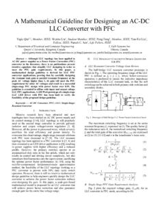
3 Frequency Jittering for Reduced EMI Signature Latching or Auto Recovery Timer Based Overload Protection Adjustable Overpower Protection (OPP) Adjustable Maximum Frequency Clamp Fault Pin for Severe Fault Conditions, NTC Compatible for OTP 4 ms Soft Start TimerPIN CONNECTIONS(Top Views)SOIC 9 NBD SUFFIXCASE 751 BPSee detailed ordering and shipping information on page 3 ofthis data INFORMATION191342abcde = Specific Device CodeA= Assembly LocationL= Wafer LotY= YearW= Work Weekf= Additional Options CodeG= Pb Free PackageMARKING DIAGRAMS1342abcdeALYWfG19 GNDDRVVCCHVFMAXFBZCD/OPPCSF ault1 FBZCD/OPPCSF aultGNDDRVVCCHV1 SOIC 8 NBD SUFFIXCASE APPLICATION SCHEMATICF igure 1. NCP1342 8 Pin Typical Application CircuitLNEMIF ilter++++ZCD/OPPFBCSGNDDRVVCCHVVoutNCP13 42 Fault t Figure 2.
4 NCP1342 9 Pin Typical Application CircuitLNEMIF ilter++++ZCD/OPPFBCSGNDDRVVCCHVVoutNCP13 42 Fault t 1. PART NUMBER DECODE NCP1342 ABCDEFNCP1342 ABCDEF*DeviceOTP/OverloadJitter Frequency /AmplitudeQuiet SkipCS MinCS Min ShiftAdditionalA AR/ARA kHz/75 mVA 800 HzA 200 mVA 400 mV B Latch/ARB kHz/92 mVB kHzB 150 mVB 350 mVAC AR/LatchC kHz/55 mVC kHzC 100 mVC 300 mVCD Latch/LatchD kHz/61 mVD DisabledD 250 mVD 250 mVDE AR/None E kHz/75 mV E DisabledE F Latch/NoneF kHz/92 mV F G kHz/55 mV G H kHz/61 mV H J kHz/75 mV K kHz/92 mV L kHz/55 mV M kHz/61 mV N Disabled *Not present in all parts. See Table 2 for 2. ADDITIONAL PART OPTIONSFD escription Default ConfigurationAX2 Discharge Disabled, VBO(stop) = 84 V, VBO(start) = 94 VDX2 Discharge Disabled, VBO(stop) = 84 V, VBO(start) = 94 V, Resettable Overload TimerEX2 Discharge Disabled, Brownout DisabledFX2 Discharge Disabled, VCC(off) Triggers Autorecovery Timer (trestart)GX2 Discharge DisabledHVBO(stop) = 84 V, VBO(start) = 94 VTable 3.
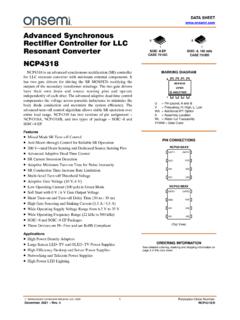
5 ORDERING INFORMATIONPart NumberDevice MarkingPackageShippingNCP1342 AMDCCDR2G1342 AMDCCSOIC 8 NB (Pb Free) NCP1342 ANDAAD1R2G1342 ANDAASOIC 9 NB (Pb Free)2500 / Tape & ReelNCP1342 DADBDD1R2G1342 DADBDNCP1342 AMDCDAD1R2G1342 AMDCDANCP1342 AMAACD1R2G1342 AMAACNCP1342 ANACED1R2G1342 ANACENCP1342 ANDBDD1R2G1342 ANDBDNCP1342 BKDCDAD1R2G1342 BKDCDANCP1342 BMDCDAD1R2G1342 BMDCDANCP1342 BMDCDD1R2G1342 BMDCDNCP1342 BMDCDDD1R2G1342 BMDCDDNCP1342 AMDCDD1R2G1342 AMDCDNCP1342 ANACCED1R2G1342 ANACCENCP1342 ENACEFD1R2G1342 ENACEFNCP1342 AMDADGD1R2G1342 AMDADGNCP1342 AMDCDHD1R2G1342 AMDCDHNCP1342 ENDCEAD1R2G1342 ENDCEANCP1342 DADBDGD1R2G1342 DADBDGNCP1342 ADDCDAD1R2G(In Development)1342 ADDCDASOIC 9 NB (Pb Free)2500 / Tape & BLOCK DIAGRAMF igure 3. NCP1342 Block DiagramFBCSRQSRFBtLEB1 OPPZCD/OPP KFBICSVDDC lampVCCDRVGNDVCCX2/BO Detect+VCCM anagementHVX2 FMAXC ontrolFaultVFB(open)On TimeControlILIM1 DetecttLEB2 ILIM2 DetectJitter RampCount 4 Abnormal OCPOPPC ontrolOPPOff TimeControlDead TimeControlValley/FFControlFBQR_FMAX ttoutQuiet SkipControlFBFaultManagementBOVCC(OVP)TS DOVLDtOVLDA bnormal OCPOVLDF aultQR_FMAXMPCMC ontrolFBOVP/OTPD etectOVPOTPOVPOTPVF ault(clamp)FaultIOTPVDDRF ault(clamp)FMAXIFMAXVDD8 Pin9 PinTable 4.
6 PIN FUNCTIONAL DESCRIPTION8 Pin9 PinPin NameFunction11 FaultThe controller enters fault mode if the voltage on this pin is pulled above or below the faultthresholds. A precise pull up current source allows direct interface with an NTC thermistor. 2 FMAXA resistor to ground sets the value for the maximum switching Frequency clamp. If this pin ispulled above 4 V, the maximum Frequency clamp is input for the QR Flyback controller. Allows direct connection to an resistor divider from the auxiliary winding to this pin provides input to the demagnetization de-tection comparator and sets the OPP compensation to the cycle by cycle current limit is the drive pin of the circuit. The DRV high current capability ( /+ A) makes it suit-able to effectively drive high gate charge power pin is the positive supply of the IC.
7 The circuit starts to operate when VCC exceeds 17 V andturns off when VCC goes below 9 V (typical values). After start up, the operating range is 9 V upto 28 V. 9N/CRemoved for creepage pin is the input for the high voltage startup and brownout detection circuits. It also containsthe line removal detection circuit to safely discharge the X2 capacitors when the line is 5. MAXIMUM RATINGSR atingSymbolValueUnitHigh Voltage Startup Circuit Input VoltageVHV(MAX) to 700 VHigh Voltage Startup Circuit Input CurrentIHV(MAX)20mASupply Input VoltageVCC(MAX) to 30 VSupply Input CurrentICC(MAX)30mASupply Input Voltage Slew RatedVCC/dt1V/msFault Input VoltageVFault(MAX) to VCC + VVFault Input CurrentIFault(MAX)10mAZero Current Detection and OPP Input VoltageVZCD(MAX) to VCC + VVZero Current Detection and OPP Input CurrentIZCD(MAX) 2/+5mAMaximum Input Voltage (Other Pins)VMAX to Input Current (Other Pins)IMAX10mADriver Maximum Voltage (Note 1)VDRV to VDRV(high)VDriver Maximum CurrentIDRV(SRC)IDRV(SNK)500800mAOperati ng Junction TemperatureTJ 40 to 125 CMaximum Junction TemperatureTJ(MAX)
8 150 CStorage Temperature RangeTSTG 60 to 150 CPower Dissipation (TA = 25 C, 1 oz. Cu, 42 mm2 Copper Clad Printed Circuit)DR2G Suffix, SOIC 8D1R2G Suffix, SOIC 9PD(MAX)450330mWThermal Resistance (TA = 25 C, 1 oz. Cu, 42 mm2 Copper Clad Printed Circuit)DR2G Suffix, SOIC 8D1R2G Suffix, SOIC 9 RqJA225300 C/WESD CapabilityHuman Body Model per JEDEC Standard JESD22 A114F (All pins except HV)Human Body Model per JEDEC Standard JESD22 A114F (HV Pin)Charge Device Model per JEDEC Standard JESD22 C101 FLatch Up Protection per JEDEC Standard JESD78E20008001000 100 VVVmAStresses exceeding those listed in the Maximum Ratings table may damage the device. If any of these limits are exceeded, device functionalityshould not be assumed, damage may occur and reliability may be Maximum driver voltage is limited by the driver clamp voltage, VDRV(high), when VCC exceeds the driver clamp voltage.
9 Otherwise, themaximum driver voltage is 6. ELECTRICAL CHARACTERISTICS: (VCC = 12 V, VHV = 120 V, VFault = open, VFB = V, VCS = 0 V, VZCD = 0 V, VFMAX= 0 V, CVCC = 100 nF , CDRV = 100 pF, for typical values TJ = 25 C, for min/max values, TJ is 40 C to 125 C, unless otherwise noted)CharacteristicsConditionsSymbolMin TypMaxUnitSTART UP AND SUPPLY CIRCUITSS upply VoltageStartup ThresholdDischarge Voltage During Line RemovalMinimum Operating VoltageOperating HysteresisInternal Latch / Logic Reset LevelTransition from Istart1 to Istart2dV/dt = V/msVCC increasingVCC decreasingVCC decreasingVCC(on) VCC(off)VCC decreasingVCC increasing, IHV = 650 mAVCC(on)VCC(X2_reg)VCC(off)VCC(HYS)VCC( reset)VCC(inhibit) (off) DelayVCC decreasingtdelay(VCC_off)253240msStartup DelayDelay from VCC(on) to DRV Enabletdelay(start)
10 500msMinimum Voltage for Start Up CurrentSourceVHV(MIN) 30 VInhibit Current Sourced from VCC PinVcc = 0 Up Current Sourced from VCC PinVcc = Vcc(on) V 40 C to 105 C 40 C to 125 Up Circuit Off State Leakage CurrentVHV = VVHV = 325 VVHV = 700 VIHV(off1)IHV(off2)IHV(off3) 152050mASupply CurrentFault or LatchSkip Mode (excluding FB current)Operating CurrentVCC = VCC(on) VVFB = 0 Vfsw = 50 kHz, CDRV = openICC1 ICC2 ICC3 Overvoltage Protection ThresholdVCC(OVP)272829 VVCC Overvoltage Protection Delaytdelay(VCC_OVP)253240msX2 CAPACITOR DISCHARGE (ALL VERSIONS EXCEPT xxxxxA, xxxxxD, xxxxxE, xxxxxF, xxxxxG)Line Voltage Removal Detection Timertline(removal)65100135msDischarge Timer Durationtline(discharge)213243msLine Detection Timer Durationtline(detect)213243msVCC Discharge CurrentVCC = 20 VICC(discharge)131823mAHV Discharge LevelVHV(discharge) 30 VBROWNOUT DETECTION (ALL VERSIONS EXCEPT xxxxxE)System Start Up ThresholdOther VersionsVersions xxxxxA, xxxxxD, xxxxxHVHV increasingVBO(start)107891129411699 VBrownout ThresholdOther VersionsVersions xxxxxA, xxxxxD, xxxxxHVHV decreasingVBO(stop)9379988410289 VHysteresisOther VersionsVersions xxxxxA, xxxxxD, xxxxxHVHV increasingVBO(HYS) VBrownout Detection Blanking TimeVHV decreasingtBO(stop)4070100msGATE DRIVERise TimeVDRV from 10% to 90%tDRV(rise) 2040nsFall TimeVDRV from 90% to 10%tDRV(fall) 530ns2.