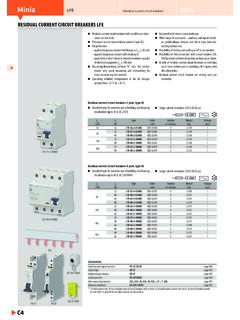
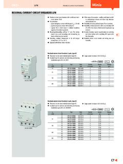
Transcription of 2P & 4P RCCBs (Residual Current Circuit Breakers)
1 2P & 4P RCCBs ( residual Current Circuit Breakers). Description poles: 2P and 4P Technical information Compact devices which provide type: A A type suitable for residual pul- RCD earth leakage protection frequency: 50Hz sating direct currents, whether (protect against electrical shocks suddenly applied or slowly rising. by direct or indirect contacts).To Connection capacity They are used whenever fault open automatically in the event 25 to 63A: currents are not sinusoidal. of an earth fault between phase rigid conductors: 25mm and earth and/or neutral and lexible conductors: 16mm Complies with EN61008-1. earth. 80 and 100A: rigid conductors: 50mm . Technical data lexible conductors: 35mm . sensitivity: High sensitivity: 30mA. instantaneous tripping (ixed) /. Medium sensitivity: 100mA, 300mA instantaneous or selective tripping (ixed). Current rating: 25 to 100A. voltage rating: 230V AC. (2P) and 400V (4P). Description Current Pack Cat.
2 Ref. rating qty 2P 4P. RCCBs A type 10mA 16A 1 CCA216U - RCCBs A type 30mA 25A 1 CDA225U CDA425U. 40A 1 CDA240U CDA440U. CDA240U 63A 1 CDA263U CDA463U. 80A 1 - CD480A. 100A 1 - CD484A. 125A 1 - CDA490. RCCBs A type 100mA 40A 1 CE240J CE440J. 63A 1 CEA263N CE463J. 80A 1 CE281J CE481J. 100A 1 CE285J CE485J. RCCBs CF440J A type Selective 100mA 100/A 1 CN284J CN484A. RCCBs A type 300mA 25A 1 CF225J CF425J. 40A 1 CF240J CF440J. 63A 1 CF263J CF463J. 80A 1 CF280C CF480C. 100A 1 CF284C CF484C. RCCBs A type Selective 300mA 80A 1 CP280E - 100A 1 CP284J CP484D. RCCBs Product presentation contact position indicator Test button (large dimensions). trip indication ergonomic operating handle Contact positioning indicator Trip indicator The mechanical indicator on the front of RCCB shows the physical The status of the RCCB can be visualised by the colour of the trip Protection Devices position of the contacts. indicator in addition to the position of the operating lever.
3 Red indication for closed contacts Grey indication for normal conditions (even when operating lever is Green indication for open contacts in ON/OFF position). Yellow indication for tripped condition, operating lever in OFF. The green indication is the guarantee that the contacts are open and position. that the terminals are not live. Similar condition exists when TEST button is pushed or RCCB is remotely tripped via protection auxiliaries. Positive contact indication Earth leakage fault indication OFF. OFF ON test green red grey yellow 2P & 4P RCCBs residual Current devices Principle A residual Current device (RCCB) is the generic term for a device which simultaneously performs the functions of detection of the re- sidual Current , comparison of this value with the rated residual operating value and opening the protected Circuit when the residual Current exceeds this value. For ixed domestic installations and similar applications we have two types : residual Current operated Circuit - breaker without integral over- Current protection ( RCCBs ) which should comply with the requirements of IEC 61 008.
4 residual Current operated Circuit - breaker with integral over- Current protection (RCBOs) which should comply with the requirements of I2. IEC 61 009. Id I1. Both RCCBs and RCBOs are further divided into types depending on their operating function : Ic Id Type AC For which tripping is ensured for residual sinusoidal alternating currents, whether suddenly applied or slowly rising. Marked with the symbol: RB RA. Type A For which tripping is ensured for residual sinusoidal Current lowing through torroid in healthy Circuit alternating currents and residual pulsating direct currents, whether Ires = I1-I2 = 0. suddenly applied or slowly rising. Marked with the symbol: Current lowing through torroid in Circuit with earth fault I3. Ires = I1-I2+I3 = I3. Type S For selectivity, with time-delay. Marked with the symbol: Whole house protection is provided typically by a consumer unit where the RCCB device serves as the main switch.
5 Although very popular this suffers from a disadvantage: all circuits are RCCBs must be protected against short-circuits by means of disconnected in the event of fault. Selective protection can be Circuit -breakers or fuses. RCBOs have their own in built short- Circuit provided by associating the RCCB with identiied high risk circuits by protection, up to it's rated value. adopting one or more of the following : The drawing opposite shows how a torroid is located around the line Split busbar consumer unit: and neutral conductors to measure the magnetic ields created by All circuits are fed via an overall isolator and selected circuits fed the Current lowing in these conductors. The sum of the magnetic additionally via the RCCB. Typical circuits fed direct are lighting, ields set up by these currents (which takes into consideration both freezer, storage heating: and circuits fed via the RCCB are socket the magnitude and phase relationship of the currents) is detected by outlets, garage circuits.
6 This concept minimises inconvenience in the torroid. the event of fault. In a normal healthy Circuit the vector sum of the Current values added Individual RCBO. together will be zero. Current lowing to earth, due to a line earth Each separate inal Circuit requiring protection by a RCD can be fault, will return via the earth conductor, and regardless of load supplied through an RCBO. This method provides the best solution conditions will register as a fault. This Current low will give rise to a for minimising inconvenience. residual Current (Ires) which will be detected by the device. Nuisance tripping It is most important that the line and neutral conductors are passed All Hager RCCBs incorporate a iltering device preventing the risk of through the torroid. A common cause of nuisance operation is the nuisance tripping due to transient voltages (lightning, line failure to connect the neutral through the device.)
7 Disturbances on other ) and transient currents (from high capacitive Circuit ). RCCBs work just as well on three phase or three phase and neutral circuits, but when the neutral is distributed it must pass through the Pulsating DC fault Current sensitive torroid. Increasingly, semi-conductors are also extensively used in computers, VDUs, printers, all of which may be fed from RCCBs are not suitable for use on DC systems and unearthed the mains electrical supply. The presence of semi-conductors may networks. result in the normal sinusoidal AC waveform being modiied. For example, the waveform may be rectiied or, as in asymmetric phase RCCBs domestic installation control devices, the waveform may be chopped. The resulting RCCBs can be installed in two ways: waveforms are said to have a pulsating DC component. 1. whole house protection. In the event of an earth fault occurring in equipment containing 2. selective protection.
8 Semi-conductor devices, there is a probability that the earth fault Current will contain a pulsating DC component. Standard type AC may not respond to this type of earth fault Current and the intended degree of protection will not be provided. RCCBs Use of RCCBs The tripping characteristic for a 30mA RCCB is also shown in the graph. It shows the level of Current required to cause the RCCB to RCCBs offer excellent protection against earth fault currents; the trip, for example; 50mA will cause a trip but not 10mA. main areas of application being as follows: Comparing its characteristic with the various zones on the graph it can be seen that the 30mA RCCB gives a very good measure of Zs value too high to allow disconnection in the required time protection against the hazards associated with electric shock. Where a higher level of protection is required, for example in laboratories, Where the overcurrent protection or a Circuit breaker cannot provide 10mA devices are available.
9 Disconnection within the speciied time because the earth fault loop IEC 60 479-1. impedance is too high the addition of RCCB protection may well mS. solve the problem without any other change in the system. Because of its high sensitivity to earth fault Current and its rapid operating 10000. time, in most cases the RCCB will ensure disconnection within the speciied time. This is achieved without any detriment to overcurrent 5000. high risk usually no discrimination because, unlike the situation in a fuse based system, harmful effects of lethal effects the increased sensitivity is obtained without increasing sensitivity to 2000. overcurrent faults. Use of RCCBs in this way can be particularly useful for construction sites and bathrooms where disconnection 1000. times are more stringent than for standard installations. (Construction 2 3 4. duration of Current flow sites - at 220-277V, bathrooms - ). 500. tripping The limitation to this technique is the requirement that the rated characteristic of residual operating Current multiplied by Zs should not exceed 50V.
10 200 30mA RCD. This is to avoid the danger of exposed conductive parts reaching an unacceptably high voltage level. 100. 50. residual Current protection can even be added to a completed distribution system where the value of Zs is excessive, either be- Protection Devices cause of a design oversight or subsequent wiring modiication. 20. Protection against shock by direct contact 10. 1 2 5 10 20 50 100 200 500 mA. So far we have considered shock by indirect contact only. body Current Direct contact is deined thus: Direct contact - contact of persons or livestock with live parts which Note : may result in electric shock. The consideration here is not the Although RCCBs are extremely effective devices they must never be hazard of parts becoming live as a result of a fault but the possibility used as the only method of protection against electric shock. With or of touching Circuit conductors which are intentionally live.