Transcription of 3D Printer User Manual - Voxelab 3D p
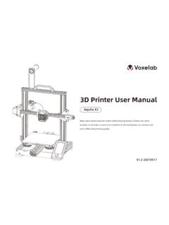
1 3D Printer user : Each device must be tested before leaving factory. If there are some residues in extruder or some tiny scratches on the build plate, it is normal and won t affect the printing to assemble AquilaUse The 3D PrinterProduct IntroductionSpare PartsStart PrintingWire connectionPrinting NoticeTrouble ShootingThank you for choosing and using the products of Voxelab Technology. For your convenience, please read this Manual carefully before use and follow the Manual strictly. The Voxelab team is always ready to provide you with the perfect service. Please contact us by email listed, if you have any can also get operational knowledge of the equipment from the following way: Voxelab website: can get the software, firmware, device maintenance and relevant contact information via Voxelab pay attention to the sharp edges and corners of the not make any modifications to the device. To avoid personal injury or property damage please ensure your operation as followed as the Guide.
2 Dress properly. Do not wear loose clothing or jewelry. Keeping your hair, clothing and gloves away from moving parts. Do not directly touch the nozzle and build plate to avoid high-temperature not operate the Aquila in flammable liquid, gas or dust environment (The high temperature generated by Aquila operation may react with dust, liquid, and flammable gas in the air to cause a fire.) Do not put the Aquila into the situation in which an unstable environment. The Printer quality will be and untrained personnel are not allowed to operate the Aquila the device in a well-ventilated environment. Some materials may produce odors during the printing process. Do not manually move the nozzle and printing platform mechanism while booting up, otherwise the device will be damaged. Never use the device for illegal use the device to make any food storage vessels. Never put the model into your mouth. To lower the build plate before loading/unloading filament. The distance between the nozzle and build plate should be kept for at least 50mm.
3 Keep the device with regular maintenance, to wipe with a dry cloth to remove dust and adhered printing items. IntroductionXE-axis kit X-axis limit switch Build plate Y-axis tensioner Extruded kit Material rack and spool holderZ-axis passive tensionerScreenKnob switchMachine basePower supply Voltage regulatorY-axis limit motorE-axis motorX-axis motorCouplingZ-axis limit switchZ-axis motor Power switch and socket ParametersModel Print sizeForming technologyNumber of nozzleLayer thicknessNozzle diameterXY axis precisionFilamentFile formatWorking modeCompatible slicing softwarePower specificationTotal powerHotbed temperatureNozzle temperatureResume printing functionFilament sensorDual z-axis screwsLanguage switchComputer operating systemPrint speedVoxelab Aquila220*220* - PLASTL / OBJ / AMFM emory card offline printing or online printingCura / Simplify 3D / VoxelMakerInput AC 115/230V 50/60Hz Output DC 24V350W 100 C 250 CYesNoNoEnglish / ChineseWindows 7/10 / Mac OS 180mm/s 30-60mm/s normally04 Spare PartsScreen kit *1 Printer base *1
4 Extruder kit *1Z-axis passive block *1X-axis tensioner *1Z-axis motor kit *1X-axis limit switch kit *1XE axis kit *1Z-axis profile(left) *1Z-axis profile(right) *1 Gantry profile *1 X-axis profile *1T-shaped screw rod *105 Spare PartsMaterial rack *1 Material pipe and nut *12020 profile cover *2 Synchronous belt *1 Remove tool *1 Cable tie *1 Needle *1 Storage card and card reader *1M6 Pneumatic joint *2 Power cable *1 Wrenches andscrewdrivers *1 Hexagon socket countersunkhead screw M4x20 *2 Hexagon socket head springwasher combination screwM5x25 *5M4 T nuts *6 Hexagon socket head springwasher combination screw M4x8 *2 Nozzle *1 Screen bracket *1 Filament *1 Hexagon socket flat roundhead screw M4x6 *2 Hexagon socket head springwasher combination screw M5x45 *5 Hexagon socket head springwasher combination screw M4x12 *4 Hexagon socket flat roundhead screw M5x14 *606 Installation of Z-axis limit switch kit and Z-axis profilesPrinter base *11 Step: Use the four pieces screws M5x45 to fix Z-axis with the profile(right) *1 Hexagon socket head springwasher combination screw M5x45 *4M5x45Z-axis profile(left) *107 Installation video can be found on Voxelab Youtube channelInstall Z-axis motor kit and T-shaped screw rod2 Step: Lock the T-shaped screw rod on the Z-axis motor component, and then use two M4x20 screws to slightly lock the Z-axis motor component on the profile (as showed above).
5 Z-axis motor kit *1T-shaped screw rod *1 Hexagon socket countersunkhead screw M4x20 *2M4x2008 Install pneumatic joint, XE-axis kit X-axis profile3 Tighten the tube connector by opening end wrench. And fix the XE-axis kit with two pieces M5x14 axis kit *1X-axis profile *1M6 Pneumatic joint *1 Open-end wrench *1 Hexagon socket flat roundhead screw M5x14 *2M5x1409 Install synchronous belt, extruder kit and Z-axis passive block4 Put the synchronous belt into the profile along the v-wheel of the extruder kit.(The belt is on the top of the profile and under the v wheel) When pushing it into the middle. Extruder kit *1 The highlighted red stripe refers to synchronous Z-axis passive axis kitZ-axis passive block *1 Hexagon socket flat roundhead screw M5x14 *1 Synchronous belt *110M5x14 Install X-axis Tensioner5X-axis tensioner *11. Disassemble the X-axis Tighten it with a plastic hand screw nut, lock Z-axis passive block with M5x14 screw first, and then lock the M5x14 Insert the synchronous belt into the tensioner block, and put it into the X-axis tensioner together with the synchronous socket head springwasher combination screw M4x8 *2 M5x14 M5x14 Hexagon socket flat roundhead screw M5x14 *2X-axis limit switch kit *111 Attention: During the current operation, please do not tighten the X-axis tensioner screws with too much X-axis Tensioner4.
6 Insert the synchronous belt buckle into the sheet metal slot at the back of the extruder and tighten X-axis tensioner Lock the X-axis limit assembly on the XE axis with two M4x8 hexagon socket head cap the Z-axis moving kit and adjust the tightness of X-axis and Y-axis tensioners6 Step 1. Make the Z-axis kit move along the V-wheel to be inserted into the two ends of the Z-axis profile (as showed in the figure above). 2. After installation, slide the extruder to see whether the X-axis can be touched and adjust the synchronous belt to its proper status. Synchronous belt moves smoothly without the first step: assembled componentsTake the second step: assembled componentsTips: Manually rotate the X-axis and Y-axis tensioners to be the approprate tightness. Refer to A and B: the difference between the nut and the screw (protrusion) is 0-2mm. The reference standard is to press the synchronous belt will a little tension. Too loose or tight belt will affect the printing effect, and too tight belt will 13 Install the gantry profile, screen kit7 Gantry profile *11.
7 Fix the profile on the upper end of the gantry with four hexagon sock head cap screws Tighten lightly the M4 T-nut and the M4-12 screw in turn by hexagon wrench, for a total of 4 4. Screen kit *1 Screen bracket *1 Hexagon socket head springwasher combination screwM5x25 *4M5x25M4x12M4 T nuts14 Connect the display screen kit with screen the screen kit directly into the screen bracket. Use the hexagon wrench to lock the four screws on the left side of the screen bracket with the machine. M4 T nuts *6 Hexagon socket head springwasher combination screw M4x12 *4 Install spool holder and gantry cover8 Step: Put flat round head M4x6 and T nuts into the material rack (as showed), place the spool holder on the rack and fix on the profile with screws (as showed); Then place the 2020 profile cover on both rack *1 Material pipe and nut *12020 profile cover *2T nuts *2 Hexagon socket flat roundhead screw M4x6 *2M4x6 Connect the filament tubeInstall it on the left15 Wire connection9 Insert the teflon tube into the pneumatic connectorAttention Damage might occur if voltage setting is incorrectly.
8 Make sure the current input voltage matches to your local power supply (115/230V). Plug in power cord and turn power switch to 1 to turn it on. Do not disconnect the cables when Aquila is powered X, E, Z-axis stepper motors according to the yellow label on the 6pin (4 wires) portConnect X, Z-axis limit switches according to the yellow label on the 3pin (2 wires) portPlug in the power cord (as showed) and toggle the switch to turn on the powerX E Z-axis motor portX Z-axis limit switchPower cable *1 X motorX-axis limit switchZ-axis limit switchE motorZ motor16 Bed Leveling10 Note: The UI information is only for reference, the actual UI may be sure the extruder homing has finished before close the the leveling process, please do not touch the Teflon tube and nozzle cable. Check the steadiness of the build plate before leveing. If the build plate is unsteady, please use open-end wrench to adjust the v-wheel to steady [Auto home] first to ensure the extuder in the home position; then choose [Disable steppers] to close the operation video can be found on Voxelab Youtube channelBed LevelingThe nozzle is too far away from the build plate, so the consumables can not adhere to the build even filament adheres right on the build plate.
9 The nozzle is too close to the build plate, the filament are not extruded sufficiently, and the nozzle is damaged to result in plug. It s easy to scratch the printing build adjusting the upper position of the 4 nuts, check the center position again. Note: If the rotating nuts can not make the nozzle touch the build plate, the position of the z-axis limit switch may be too high; please adjust it Move the extruder on the top of the leveling nut. Screw the nut and adjust the distance between the nozzle and the build plate. The distance is around (Thickness of a piece of A4 paper)2. Use a piece of A4 paper to assist in leveling, so that the nozzle can just scratch the A4 paper lightly. Adjust the leveling nuts on the four sides in turn until you can feel the slight resistance from the nozzle when pulling the A4 Test the distance between the nozzle and the print platform is enough or not. Repeat the above steps 1-2 times if 111 Method 2 Note: The UI information is only for reference, the actual UI may be : The printing preheat temperature settings have been done.
10 PLA: nozzle temperature 200 C, hot bed temperature 60 C. ABS: nozzle temperature 240 C, hot bed temperature 70 C. For other materials or under some conditions, please adjust the parameters at the interface home page Control - Temperature - PLA/ABS preheat the filament12 For better printing, the end of filament is as showed in the When waiting for the temperature to rise, please hang the filament on the material Press the spring to pull filament pass through (loose the spring and pull filament back and forth to see if extrusion pressure is too high or too low; adjust the screw on the force arm if the pressure is improper).3. Pull filament into the wire tube; click <automatic input> button beneath the setting to send filament to the nozzle. Loading is completed when filament are extruded at the nozzle. Filament can be extruded to the nozzle manually when Aquila is 20 Load the filamentReplace the filament during printing1. If filament in the nozzle, heat up the nozzle to 185 C+, draw out the filament to replace To replace filament during the printing process, please adjust the printing speed to 10%, then replace it as introduced in Step the filament into this position21 Start printing13 File names must be Latin letters or numbers, Chinese characters and other special symbols are the slice software on the finish leveling first before printing, please level the build plate first, otherwise it will easily cause nozzle damage, plug and scratch the build the TF card, press the knob and set up the menu to print the printingPrintNote: When you notice the improper distance between the nozzle and the build plate during printing the first layer, please click the setting button to perform the z-axis the offset value is positive, the nozzle and the build plate gets farther.