Transcription of AN 455: Understanding CIC Compensation Filters
1 Altera Corporation Note 455 Understanding CICC ompensation FiltersIntroductionThe cascaded integrator-comb (CIC) filter is a class of hardware-efficient linear phase finite impulse response (FIR) digital Filters . CIC Filters achieve sampling rate decrease (decimation) and sampling rate increase (interpolation) without using multipliers. Altera s CIC Compiler MegaCore function implements various CIC Filters based on Hogenauer s Filters were first proposed by Eugene Hogenauer in 1981, For more information about CIC Filters , refer to Eugene B. Hogenauer, An economical class of digital Filters for decimation and interpolation, IEEE Transactions on Acoustics, Speech and signal processing , pp.
2 155-162, April CIC filter consists of an equal number of stages of ideal integrator Filters and comb Filters . Its frequency response may be tuned by selecting the appropriate number of cascaded integrator and comb filter pairs. The highly symmetric structure of a CIC filter allows efficient implementation in hardware. However, the disadvantage of a CIC filter is that its pass band is not flat, which is undesirable in many applications. Fortunately, this problem can be alleviated by a Compensation application note presents theory and methods for designing CIC compensating Filters for sample rate conversion systems.
3 The MATLAB signal processing Toolbox is used to design the coefficients of the compensating FIR Filters . This application note also describes how to choose parameters for designing a Compensation filter and then implements an example decimation system using the Altera CIC Compiler MegaCore function and the FIR Compiler MegaCore following topics are discussed in this document: Prerequisites on page 2 CIC filter Structure on page 2 CIC Compensation filter Design on page 4 Data Rate Down Conversion Example on page 11 Conclusion on page 17 April 2007, ver.
4 Altera CorporationPreliminaryUnderstanding CIC Compensation FiltersPrerequisitesThis document targets digital signal processing (DSP) systems engineers who must design CIC Compensation Filters for rate conversion basic knowledge of DSP and digital filter design will help you understand the trade-off between various CIC Compensation filter design addition, to understand and duplicate the examples and figures used in this application note, you should have the following.
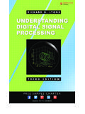
5 Some experience with MATLAB and SIMULINK Some knowledge of Altera DSP Solutions, including DSP Builder1 The design example used in this application note can be found CIC filter StructureThe basic elements of a CIC filter are integrator Filters and comb Filters , as shown in Figure 1. Block Diagram of Three-Stage CIC Decimation and Interpolation FiltersAltera Corporation 3 PreliminaryCIC filter StructureAn integrator filter is a single pole accumulator with a transfer function HI(z) (Equation 1):(1)A comb filter is a differentiator with a transfer function HC(z) (Equation 2):(2)In this equation, M is the differential delay, and is usually limited to 1 or a CIC filter , the integrators operate at high sampling frequency (fS), and the comb Filters operate at low frequency (fS/R).
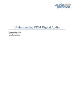
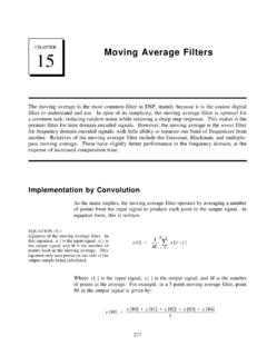
6 Using the Noble identities, the equivalent frequency response of their cascade can be calculated (Figure 2).Figure 2. Block Diagram of the Equivalent Frequency Response of an N-Stage CIC FilterEquation 3 shows the total response of a CIC filter at high frequency (fS):(3)In this equation, N is the number of integrator-comb filter pairs, and R is the rate change factor. Equation 3 implies that the equivalent time domain impulse response of a CIC filter can be viewed as a cascade of N rectangular pulses. Each rectangular pulse has RM ()11z1 ----------------=Hcz()1zM =Hz()HINz()HcNzR()zk k0=RM 1 N==4 Altera CorporationPreliminaryUnderstanding CIC Compensation FiltersEquation 4 shows the magnitude response of an N-stage CIC filter at high frequency (fS):(4)Figure 3 shows an example of a CIC filter magnitude response:Figure 3.
7 Magnitude Response of a CIC filter with N = 9, R = 8, and M = 1fFor more information about CIC Filters , refer to Matthew Donadio, Cascaded Integrator-Comb (CIC) filter Introduction, available at Compensation filter DesignFigure 3 shows that when the number of stages is large, the CIC filter frequency response does not have a wide, flat pass band. To overcome the magnitude droop, a FIR filter that has a magnitude response that is the inverse of the CIC filter can be applied to achieve frequency response correction. Such Filters are called Compensation Filters .
8 For data rate down conversion, the Compensation filter follows the CIC filter . For up sampling systems, the Compensation FIR filter pre-conditions the data and is followed by a CIC filter . In other words, the Compensation filter always operates at the lower rate in a rate conversion Hf() Mf()sin fR----- sin-----------------------N=Altera Corporation 5 PreliminaryCIC Compensation filter Designdesign. One benefit of running the Compensation filter at the low rate is to achieve a more efficient hardware solution, that is, more time sharing in the Compensation FIR 4 gives the magnitude response of a CIC filter .
9 To achieve a flat pass band, the Compensation FIR filter should have a magnitude response that is the inverse of Equation 4, as shown in Equation 5:(5)When R is large, the Compensation filter response can be approximated by the inverse sinc function, so the Compensation filter is sometimes referred to as the inverse sinc filter . In some rate change systems, Compensation Filters are also multirate Filters . They can implement additional decimation or interpolation as necessary, but usually by a factor of 2 or Compensation filter Coefficients Using MATLABAny filter design tool that generates filter coefficients based on the specified frequency response can be used to design a CIC Compensation filter .
10 In this application note, the MATLAB signal processing Toolbox function fir2 is used to generate the coefficients for CIC Compensation fir2 function designs FIR Filters with an arbitrary frequency response based on the frequency sampling method. The generated filter coefficients are real and symmetric. You can specify a digital FIR filter order L with the frequency response specified by vectors F (frequency) and A (magnitude response on break points F). The fir2 function returns an (L+1) vector of filter MATLAB script provided in this application note is automatically generated by the Altera CIC Compiler MegaCore function, version more information about the frequency sampling method, refer to Rabiner, B.