Transcription of Application Note - Solid State Optronics
1 Application Note 040. Solid State Relays vs. Electromechanical Relays Application Note Solid State Relays vs. Electromechanical Relays Introduction package size of an EMR can limit the size of a PCB design. Isolation voltage is another area where EMRs are limited. Most In a relay's most basic function, the switching of a load circuit is EMRs are typically rated for minimum input to output isolation controlled by a low power, electrically isolated input signal. In voltages of 1500 to 2000 VAC. the past, Electromechanical Relays (EMRs) have been the component of choice, largely due to price, function, and Load Contacts availability. Now, however, the emergence of semiconductor technology has provided the means to manufacture Solid State Arm relays (SSRs) which in many applications outperform their predecessors.
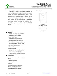
2 Spring Lever Solid State relays provide the advantages of almost infinite Input switching lives, bounce-free operation, immunity to EMI, higher Coil operating speeds, low level control signals, small package size, Core and multi-function integration. These advantages can save the design engineer board space, component count, time and money while improving product life, performance, and reliability. Solid State Optronics (SSO) has been a leader in the design, Figure 01: Electromechanical Relay (EMR). development, and production of low cost, high performance The Solid State Relay SSRs for more than 30 years. SSO offers a wide range of MOSFET, SCR, and Triac based relays, complemented by a Figure 02 shows the topology of a typical 1 Form A, MOSFET.
3 Growing selection of additional isolation components including based SSR. An input current is applied to the LED, which in optocouplers and IGBT/Triac/MOS drivers. By reducing cost most cases is a Gallium Arsenide (GaAs) infrared LED. The and package size while increasing function and performance, emitted light is reflected within an optical dome, generally Solid State relays from SSO now serve as a viable and superior constructed of a gel-like lensing material, onto a series of photo option to electromechanical relays. diodes. The photodiodes generate a resulting voltage which, through driver circuitry, is used to control the gates of two This Application note will compare the operation of a typical EMR MOSFETs.
4 To that of a Solid State relay, and examine advantages of each in Load different types of applications. Output MOS. Gates Description + Input The Electromechanical Relay Driver Figure 01 shows the topology of a typical electro-mechanical Circuit relay. An input voltage is applied to the coil mechanism. The input voltage magnetizes the core which pulls the arm towards it. - Input This action causes the output contacts to touch, closing the load circuit. When the input voltage is removed, the spring lever will push the contacts away from each other, breaking the load Load circuit connection. Photodiode Array Inherent in its design, the EMR must make mechanical contacts in order to switch a load.
5 At the point of these contacts, Figure 02: Solid State Relay (SSR). oxidation breakdown occurs over extended life cycling (typically 106 operations), and the relay will need to be replaced. When All of the components of a Solid State relay are fabricated out of an EMR is activated, bounce occurs at the contact site. Bounce semiconductor material and as a result, the SSR combines creates a window of time where the load circuit is flickering many operational characteristics not found in other types of between open and closed, a condition which may need to be devices. Because there are no moving parts, Solid State relays considered in load design. Because there are internal have established switching lives of more than 1010 cycles, and mechanical components with physical dimension restraints, the exhibit bounce-free operation.
6 The input LEDs require low 2014 Solid State Optronics San Jos , CA Page 1 of 3 AppNote 040. + Rev 02 (11/10/2014). 002183. Application Note 040. Solid State Relays vs. Electromechanical Relays signal levels (<5mA, and in some cases <1mA) to guarantee bounce free operation increases reliability and ensures operation, making SSRs ideal for TTL and CMOS controlled consistent load control. circuits or products where low power consumption is a necessity. - Isolation Voltage: Again, by the characteristics of The input to output isolation of Solid State relays is determined construction, the Solid State relay will almost always exhibit by material properties of the molding compound and lensing higher input to output isolation voltages than an material, as well as the package size.
7 These properties allow for electromechanical relay. For many telecommunication and minimum isolation voltages of 2500 VAC and up to 5000 VAC in medical and industrial applications, a minimum of 5000 VAC. many cases. As semiconductor technology has developed is desired, clearly making the SSR the optimal choice in smaller and smaller components, the overall package size of telecom design. Solid State relays has shrunk, allowing the designer to conserve PCB space, and makes them valuable in applications where - On Resistance: Low On Resistance (RON) used to be a board space is critical. feature available only to Electromechanical Relays. With the advent of newer technology the gap between SSR and EMR resistances has closed and some relays from Solid SSR Output Types State Optronics now boast resistances well below 100m.
8 The most common SSR output type is the low threshold The low On Resistance values of SSRs allow for greater MOSFET. Low threshold devices are more easily controlled by load current capability and less signal attenuation. the driver circuitry, and allow for fast turn-on times (<500 S). Design of the driver circuitry also permits fast MOSFET gate - Output Capacitance: Electromechanical relays typically discharge, translating into quick turn-off times (<50 S). Two have an output capacitance of less than 1 pF, whereas MOSFETs inversely connected in series allows for bi-directional SSRs typically have a capacitance of greater than 20 pF. control of DC and AC signals with frequencies into the RF range.
9 Capacitance becomes an issue in high frequency signals, Typical blocking voltages range from 60 VPP to 1200 VPP, with and EMRs are a better option for HF applications. With continuous loads of up to 6 amps. newer developments in MOSFET technology, SSO does offer a range of relays suited for higher frequency A second type of SSR output is the silicon controlled rectifier applications. (SCR). This type of output is designed for AC loads only, and exhibits tight, zero-volt switching. High dV/dt characteristics - Package Dimensions: The internal components of the allow this type of device to control highly inductive loads (PF > relays control the overall package dimensions. Because ), and driver circuit design prevents false triggering.
10 Typical there are mechanical parts (coil, core, arm, contact lever blocking voltages range from 400 Vpp to 800 Vpp, with arms, spring mechanism) within the EMR, the package size continuous loads of up to is limited to the physical dimensions of functional internal components. The SSR on the other hand, is limited to only A third type of SSR output is the TRIAC based output. This type the size of the semiconductor components, and is clearly of output is also designed for AC loads only but can be capable of being manufactured in a much smaller package. controlled by either random phase or zero volt switching circuitry. Typical blocking voltages range from 400 Vpp to 800 Vpp, with continuous loads of up to Why Solid State Relays?