Transcription of Series 1240 VAC Solid State Relay - Crydom
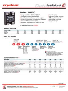
1 1-DC Series Ratings from 7 A to 40 A @ 200 VDC and from 7 A to 10 A @ 500 VDC mosfet output UL Approved, CE Compliant to EN60950-1 Improved SEMS screw and washer Redesigned housing with anti-rotation barriersFor Generation 3 datasheet click here DC control EMC Compliant to Level 3 Epoxy Free DesignPRODUCT SELECTIONLoad Voltage7 A10 A12 A20 A40 A100 VDC D1D07D1D12D1D20D1D40200 VDC D2D07D2D12D2D40400 VDC D4D07D4D12500 VDC D5D07D5D10 AVAILABLE OPTIONSNot all part number combinations are Crydom Technical Support for information on the availability of a specific part number.*Required for valid part numberFor options only and not required for valid part numberSeriesOperating Voltage1D: 1-100 VDC2D: 1-200 VDC4D: 1-400 VDC5D: 1-500 VDCR ated Load Current07: 7 Amps10: 10 Amps (500 VDC only)12: 12 Amps (not for 500 VDC)20: 20 Amps (100 VDC only)40: 40 Amps (100 & 200 VDC only)D071 DTerminationBlank: Screws & clampsK.
2 Installed standoffs with screws for PC Board mounting (1)KOUTPUT SPECIFICATIONS(2)Description7 A7 A12 A40 A12 ARecommended Operating Voltage [Vdc]1-721-721-1501-3001-385 Absolute Maximum Rating [Vdc]100100200400500 Maximum Off- State Leakage Current @ Rated Voltage [mA] Load Current [Adc] (3)12401277 Minimum Load Current [mA] (4)11111 Maximum Surge Current (10msec) [Adc]28106311819 Maximum On- State Voltage Drop @ Rated Current [Vdc] On- State Resistance [RDS-ON] [Ohms] Resistance Junction to Case (Rjc) [ C/W] Heat Sink for Rated Current @ 40 C [ C/W]3132112 A40 A7 A20 A7 110 Pulse Width Modulation Frequency [Hz] (5)40002500200012001100500035003500950 900900 INPUT SPECIFICATIONS(2)DescriptionDC ControlControl Voltage VDCM aximum Reverse Voltage-32 VDCM inimum Turn-On Voltage (6) VDCMust Turn-Off Voltage 1 VDCM inimum Input Current (for on- State ) 10 mA Maximum Input Current 15 mANominal Input Impedance Current RegulatedMaximum Turn-On Time [ sec]100 Maximum Turn-Off Time [ sec] 100Do not forget to visit us at: 2018 Crydom Inc.
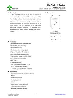
3 Specifications subject to change without MountGENERAL SPECIFICATIONS(2)ParametersDescriptionDi electric Strength, Input/ output /Base (50/60Hz)3750 VrmsMinimum Insulation Resistance (@ 500 VDC)109 OhmsMaximum Capacitance, Input/Output8 pFAmbient Operating Temperature Range (7)-40 to 100 CAmbient Storage Temperature Range-40 to 125 CWeight (typical) oz ( g)Housing MaterialUL94 V-0 Baseplate MaterialAluminumInput Terminal Screw Torque Range (in-lb/Nm)13-15 Load Terminal Screw Torque Range (in-lb/Nm)18-20 / Terminal Screw Torque Range (in-lb/Nm) (1)w/ K option 8-10 / Mounting Screw Torque Range (in-lb/Nm)18-20 / per IEC60068-2-7893% non-condensingMTBF (Mean Time Between Failures) at 40 C ambient temperature (8)21,395,130 hours (2,441 years)MTBF (Mean Time Between Failures) at 60 C ambient temperature (8)11,545,504 hours (1,317 years)WIRING DIAGRAMR ecommended Wire SizesTerminalsWire Size( Solid / Stranded)Wire Pull-OutStrength (lbs)[N]InputOutput24 AWG ( mm2) / [minimum]2 x 12 AWG ( mm2) / [maximum]20 AWG ( mm2) / [minimum]2 x 10 AWG ( mm2) / x 8 AWG ( mm2) / [maximum]10 [ ]90 [400]30 [133]110 [490]90 [400]14+2+3S OLID S T A T E R ELAYOUTPUTINPUTLoad+-V+-V+14+2+3S OLID S T A T E R ELAYOUTPUTINPUT-+V+-VLoad+* Inductive loads must be diode suppresed.
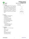
4 ** EQUIVALENT CIRCUIT BLOCK DIAGRAMS-DC+DC-DCTriggerCircuitControlCi rcuit+DC43124312024681012140510152025303 5 Input Current vs Input VoltageStandard Regulated DC InputsInput Current (mA)DC Input VoltageDo not forget to visit us at: 2018 Crydom Inc. Specifications subject to change without MountInput/ output Terminal Screw Thread Size#6-32 UNC / #8-32 UNCMECHANICAL SPECIFICATIONS(2)GENERAL NOTES (1)Tolerances: in / mmAll dimensions are in: inches [millimeters]Screw Termination1 output +2S OLID S T A T E R ELAY4 INPUT+ [ ] [ ]Mounting Hole/Slot [ ] [ ] [ ] [ ] [ ] [ ] [ ]Hex Standoff Termination ( K Option)1 output +2S OLID S T A T E R ELAY4 INPUT+ [ ] [ ]Mounting Hole/Slot [ ] [ ] [ ] [ ] [ ] [ ] [ ](4 places) [ ] [ ](2 places)(2 places)(1) Option K is designed and tested for use with printed circuit boards or ring/fork terminals having a thickness between and inches ( to mm).
5 (2) All parameters at Tc=25 C unless otherwise specified. (3) Heat sinking required, see derating curves. (4) Low current loads and high ambient temperature can affect turn-on time.(5) 8 VDC Minimum control voltage. Resistive loads only. Consider switching losses; at maximum frequency reduce to 75% output current.(6) Increase minimum voltage by 1V for operations from -20 to -40 C.(7) Decrease maximum control voltage C above 80 C ambient temperature.(8) All parameters at 50% power rating and 100% duty cycle (contact Crydom tech support for detailed report). For additional information or specific questions, contact Crydom Technical Current (Amp)Surge Duration (msec) Current (Amp)Surge Duration (msec) Current (Amp)Surge Duration (msec) Current (Amp)Surge Duration (msec) D1D40 SURGE CURRENT INFORMATIONS ingle Pulse (i)Duty Factor (10%) (ii)Duty Factor (20%) (ii)Duty Factor (50%) (ii)Do not forget to visit us at: 2018 Crydom Inc.
6 Specifications subject to change without MountSURGE CURRENT INFORMATIONS ingle Pulse (i)Duty Factor (10%) (ii)Duty Factor (20%) (ii)Duty Factor (50%) (ii) Current (Amp)Surge Duration (msec) Current (Amp)Surge Duration (msec) Current (Amp)Surge Duration (msec) Current (Amp)Surge Duration (msec) Current (Amp)Surge Duration (msec) Current (Amp)Surge Duration (msec) Current (Amp)Surge Duration (msec) D5D10 Duty Factor 10%Duty Factor 20%Duty Factor 50%PeriodPulseWideFor Pulse Wide Modulation applications select the curve according duty factor and pulse duration as following. (i) for Single Surge Pulse Tc=40 C ;Tj 175 C(ii) for Repetitive Surge Pulse Tc=40 C ;Tj 130 C Duty Factor =Pulse Wide Periodx100 (%)Do not forget to visit us at: 2018 Crydom Inc.
7 Specifications subject to change without MountTHERMAL DERATE INFORMATION(iii) SSR metal base plate acting as heat sink, it must be exposed to free ambient Current (Amps)Ambient Temperature ( C)D1D075 C/WNo Heat Sink(iii)048122030405060708090100D1D123 C/W5 C/WNo Heat Sink(iii)Load Current (Amps)Ambient Temperature ( C)051015202030405060708090100D1D202 C/W3 C/WNo Heat Sink(iii)Load Current (Amps)Ambient Temperature ( C)0102030402030405060708090100D1D401 C/W3 C/W5 C/WLoad Current (Amps)Ambient Temperature ( C)012345762030405060708090100D2D073 C/W5 C/WNo Heat Sink(iii)Load Current (Amps)Ambient Temperature ( C)0246812102030405060708090100D2D123 C/W5 C/WNo Heat Sink(iii)Load Current (Amps)Ambient Temperature ( C) C/W5 C/WLoad Current (Amps)Ambient Temperature ( C)0246812102030405060708090100D4D121 C/W2 C/W5 C/WLoad Current (Amps)Ambient Temperature ( C)012345762030405060708090100D4D072 C/W3 C/WNo Heat Sink(iii)Load Current (Amps)Ambient Temperature ( C)012345762030405060708090100D5D071 C/W3 C/W5 C/WLoad Current (Amps)Ambient Temperature ( C)02468102030405060708090100D5D10 Load Current (Amps)Ambient Temperature ( C) C/W2 C/W5 C/WDo not forget to visit us at: 2018 Crydom Inc.
8 Specifications subject to change without MountAGENCY APPROVALSEN60950-1: Meets the requirements of : 1,7: : : : : :IEC 61000-4-2 Electrostatic Discharge Level 3 IEC 61000-4-4 Electrically Fast Transients Level 3 IEC 61000-4-5 Electrical Surges Level 3 Vibration Resistance: IEC 60068-2-6 : Amplitude Range 10-55 Hz, Displacement Shock Resistance: IEC 60068-2-27 : Peak Acceleration 15g, Duration11msecE116950 Part number: KS101 Clear plastic cover compatible with all new S1 designs. Safety covers provide added protection from electric shock when installing or checking CoverHardware KitPart number: HK4 Bag with 2 square brass accessories and 2 screw 8-32 x 5/8 for output . Used to mount TMR1 lug Accessories!
9 Protective Cover & Hardware KitsRecommended AccessoriesCoverHardwareKitHeat SinkPart Resistance[ C/W]Lug TerminalThermal PadKS101HK1HK4HS501 DRHS301 / HS301 DRHS251HS201 / HS201 DRHS202 / HS202 DRHS172HS151 / HS151 DRHS122 / HS122 DRHS103 / 013118 ECN#20400Do not forget to visit us at: 2018 Crydom Inc. Specifications subject to change without MountDo not forget to visit us at: 2018 Crydom Inc. Specifications subject to change without MountDANGER / PELIGRO / DANGER /GEFAHR / PERICOLO / HAZARD OF ELECTRIC SHOCK, EXPLOSIO N, OR ARC FLASH. Di sconnect all power b efore insta lling or working with th is equipment. Verify all connecti ons and r eplace a ll covers b efore tu rning o n t o f ollow these in structio ns will result in d eath or s erio us inju ry.
10 RIESGO DE DESCARGA ELECTRICA O EXPLOSIO N. Desconecta r to dos los suministr os d e energia a e ste equipo antes de tr abajar con e ste equipo. Verificar todas las conexiones y colocar todas las tapas antes de energizer el in cumplimie nto de e stas in struccio nes puede p rovocar la muerte o le sio nes s eria DE DESCHARGE ELECTRIQUE OU EXPLOSION Ete indre to ute s les sources d' nergie de cet a ppareil avant de tr availler dessus d e c et appareil V rifier tousconnections, etremettre tous couverts enolace avant demettre sousDe n on-suiv i de ces instructio ns provoquera la mort o u d es l sio ns s rieuses s EIN ES ELEKTRISCHEN SCHLAGES ODER EINER EXPLOSIO N. Ste llen Sie jeglichen Str om a b, d er dieses G er t versorgt, bevor S ie an dem Ger t Arbeiten durchf hren Vor d em Dr ehen auf Energie alle Anschl sse berpr fen und alle Abdeckungen ssung die ser Anweisungen k nnen z um Tode o der z u schwerenVerle tzungen f DI SCOSSA ELETTRICA O DELL E SPLOSIONE.