Transcription of Automatic Street Light Control System Using …
1 Automatic Street Light Control System Using Microcontroller MUSTAFA SAAD, ABDALHALIM FARIJ, AHAMED SALAH and ABDALROOF ABDALJALIL Department of Control Engineering College of Electronic Technology/ Baniwalid Baniwalid- Libya LIBYA Abstract: - This paper aims at designing and executing the advanced development in embedded systems for energy saving of Street lights. Nowadays, human has become too busy, and is unable to find time even to switch the lights wherever not necessary. The present System is like, the Street lights will be switched on in the evening before the sun sets and they are switched off the next day morning after there is sufficient Light on the roads. this paper gives the best solution for electrical power wastage. Also the manual operation of the lighting System is completely eliminated. In this paper the two sensors are used which are Light Dependent Resistor LDR sensor to indicate a day/night time and the photoelectric sensors to detect the movement on the Street .
2 The microcontroller PIC16F877A is used as brain to Control the Street Light System , where the programming language used for developing the software to the microcontroller is C-language. Finally, the System has been successfully designed and implemented as prototype System . Key-Words: - Street Light , LDR, photoelectric sensor, microcontroller, energy saving and circuit design. 1 Introduction The idea of designing a new System for the streetlight that do not consume huge amount of electricity and illuminate large areas with the highest intensity of Light is concerning each engineer working in this field. Providing Street lighting is one of the most important and expensive responsibilities of a city. Lighting can account for 10 38% of the total energy bill in typical cities worldwide [1]. Street lighting is a particularly critical concern for public authorities in developing countries because of its strategic importance for economic and social stability.
3 Inefficient lighting wastes significant financial resources every year, and poor lighting creates unsafe conditions. Energy efficient technologies and design mechanism can reduce cost of the Street lighting drastically. Manual Control is prone to errors and leads to energy wastages and manually dimming during mid night is impracticable. Also, dynamically tracking the Light level is manually impracticable. The current trend is the introduction of automation and remote management solutions to Control Street lighting [2]. There are various numbers of Control strategy and methods in controlling the Street Light System such as design and implementation of CPLD based solar power saving System for Street lights and Automatic traffic controller [1], design and fabrication of Automatic Street Light Control System [3], Automatic Street Light intensity Control and road safety module Using embedded System [4], Automatic Street Light Control System [5], Intelligent Street Lighting System Using Gsm [6], energy consumption saving solutions based on intelligent Street lighting Control System [7] and A Novel Design of an Automatic Lighting Control System for a Wireless Sensor Network with Increased Sensor Lifetime and Reduced Sensor Numbers[8].
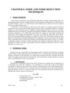
4 In this paper two kinds of sensors will be used which are Light sensor and photoelectric sensor. The Light sensor will detect darkness to activate the ON/OFF switch, so the streetlights will be ready to turn on and the photoelectric sensor will detect movement to activate the streetlights. LDR, which varies according to the amount of Light falling on its surface, this gives an inductions for whether it is a day-night time, the photoelectric sensors are placed on the side of the road, which can be controlled by microcontroller PIC16f877A. The photoelectric will be activated only on the night time. If any object crosses the photoelectric beam, a particular Light will be automatically ON. By Using this as a basic principle, the intelligent System can be designed for the perfect usage of streetlights in any place. The block diagram of Street Light System as shown in Fig.
5 1 consists of microcontroller, LDR, and photoelectric sensor. By Using the LDR we can operate the lights, when the Light is available Mathematical Methods and Optimization Techniques in EngineeringISBN: 978-960-474-339-192then it will be in the OFF state and when it is dark the Light will be in ON state, it means LDR is inversely proportional to Light . When the Light falls on the LDR it sends the commands to the microcontroller that it should be in the OFF state then it switch OFF the Light , the photoelectric sensor will be used to turn ON or OFF the Light according to the presence or absent of the object. All these commands are sent to the controller then according to that the device operates. We use a relay to act as an ON/OFF switch. Fig. 1 Block diagram of Street Light System 2 Automatic Street Light System circuit design The System basically consists of a LDR, Photoelectric sensor, Power supply, Relays and Micro controller.
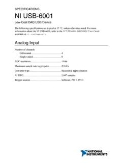
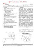
6 LDR The theoretical concept of the Light sensor lies behind, which is used in this circuit as a darkness detector. The LDR is a resistor as shown in Fig. 2, and its resistance varies according to the amount of Light falling on its surface. When the LDR detect Light its resistance will get decreased, thus if it detects darkness its resistance will increase. Fig. 2 LDR Photoelectric Sensor To detect the movement in the Street , the photoelectric sensors have been used in this paper, where emitter and receiver are in one unit as shown in Fig 3. Light from the emitter strikes the target and the reflected Light is diffused from the surface at all angles. If the receiver receives enough reflected Light the output will switch states. When no Light is reflected back to the receiver the output returns to its original state.
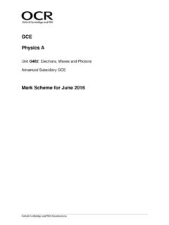
7 In diffuse scanning the emitter is placed perpendicular to the target. The receiver will be at some angle in order to receive some of the scattered (diffuse) reflection. The photoelectric sensor specifications are illustrated in Table 1. Fig. 3 Photoelectric sensor Table 1 Photoelectric sensor specifications Photoelectric Sensors (MC005) Sensing range 3-80 cm Sensing object Translucency, opaque Supply voltage, current DC 5V, 100mA Output operation Normally open Output DC three-wire System (NPN) Diameter, Length 18mm, 45mm Ambient temperature -25_70 Regulated Power Supply Usually, we start with an unregulated power supply ranging from 9volt to 12volt DC. To make a 5volt power supply, KA8705 voltage regulator IC as shown in Fig. 4 has been used. Fig. 4 Power supply regulator The KA8705 is simple to use. Simply connect the positive lead form unregulated DC power supply (anything from 9 VDC to 24 VDC) to the input pin, connect the negative lead to the common pin and Mathematical Methods and Optimization Techniques in EngineeringISBN: 978-960-474-339-193then turn on the power, a 5 volt supply from the output pin will be gotten.
8 Relays Relays are remote Control electrical switches that are controlled by another switch, such as a horn switch or a computer as in a power train Control module. Relays allow a small current flow circuit to Control a higher current circuit. Several designs of relays are in use today, 3-pin, 4-pin, 5-pin, and 6-pin, single switch or dual switches. Relays which come in various sizes, ratings, and applications, are used as remote Control switches. Fig. 5 shows different types of relays. In this paper, the 4-pin relay will be used. Fig. 5 Different types of relays PIC16F877A Microcontroller A microcontroller is a computer Control System on a single chip. It has many electronic circuits built into it, which can decode written instructions and convert them to electrical signals. The microcontroller will then step through these instructions and execute them one by one.
9 As an example of this a microcontroller we can use it to controller the lighting of a Street by Using the exact procedures. microcontrollers are now changing electronic designs. Instead of hard wiring a number of logic gates together to perform some function we now use instructions to wire the gates electronically. The list of these instructions given to the microcontroller is called a program. There are different types of microcontroller, this project focus only on the PIC16F877A Microcontroller where it's pins as shown in Fig. 6. Fig. 6 Pin diagram of PIC16F877A microcontroller 3 Automatic Street Light Control Circuit Design The inputs in the streets lighting System are LDR and photoelectric sensors, after dusk the Light sensor will activate the System , to be ready to detect any object by photoelectric sensors, on the road to turn ON the streetlights.
10 Lamps will be used as streetlights in this paper. In this section each circuit, which has been designed will be discussed. Firstly the LDR circuit as shown in Fig. 7, the LDR and RV1 form one arm of the bridge, and R1-R2 form the other arm. These arms can actually be regarded as potential dividers, with the R1-R2 arm applying a fixed half-supply voltage to the non-inverting input of the op-amp, and with the LDR-RV1 divider applying a Light -dependent variable voltage to the inverting terminal of the op-amp. Fig. 7 LDR circuit In use, RV1 is adjusted so that the LDR-RV1 voltage rises fractionally above that of R1-R2 as the Light intensity rises to the desired trigger lever, and under this condition the op-amp output switches to negative saturation and thus drives the relay on via Q1 and biasing resistors R3-R4 when the Light Mathematical Methods and Optimization Techniques in EngineeringISBN: 978-960-474-339-194intensity falls below this level, the op-amp output switches to positive saturation.