Transcription of UCC24612 High Frequency Synchronous Rectifier Controller
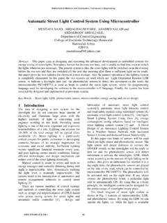
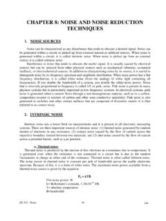
1 Copyright 2017, texas instruments IncorporatedVDDVGVSVDREGVoutCopyright 2017, texas instruments IncorporatedVDDVGVSVDREGP roductFolderOrderNowTechnicalDocumentsTo ols &SoftwareSupport &CommunityAn IMPORTANTNOTICEat the end of this datasheetaddressesavailability,warranty, changes,use in safety-criticalapplications,intellectual propertymattersand AUGUST2017 REVISEDFEBRUARY2018 UCC24612 High FrequencySynchronousRectifierController1 1 Features1 SupportsTopologiessuchas ActiveClampFlyback,QR, DCM,CCMF lybackand LLC MOSFETVDSS ensingup to 230 V OperatingFrequencyUp to 1 MHz 1 MHzfor UCC24612 -1 800 kHz for UCC24612 -2 WideVDDR angeAllowsfor DirectBiasfrom5-Vto 28-VOutputSystems 4-A Sink.
2 1-A SourceGateDriverwithProportionalGateDriv e AdaptiveMinimumOff-timefor IncreasedNoiseImmunity CycleLimitPre-Turn-offImprovesEfficiency inCCM Highor Low-SideConfigurable AutomaticLight-Loadand Sleep-ModeManagementwith 320- A standbycurrent 16-nsTypicalTurnoffPropagationDelay ReducedDrivingLoss2 Applications AC-to-DCAdapters USBType-Cand PowerDeliveryAC Adapters Serverand TelecomPowerSupply AC-to-DCAuxiliaryPowerSupply3 DescriptionUCC24612is a highperformancesynchronousrectifiercontr ollerand driverfor standardand near-idealdiodeemulationUCC24612reducesl ossesof the outputrectifierandindirectlythe primaryside drainto source(VDS) sensingcontrolschemeallowsUCC24612towork with multipletopologies,suchas ActiveClampFlyback,QR/DCM/CCMF lybackand LLC, designeffort,enablingUCC24612to excelin a varietyof wideoperatingVDDand VD voltagerangesenablesimpleimplementationi n systemswithoutputsup to 28 V.
3 Efficiencyand continuousconductionmode(CCM)is furtherenhancedwithproportionalgate-driv eand CCMcyclelimit fast comparatorwith part of agreatersystemthatmeetsstringentefficien cystandardssuchas Departmentof Energy(DoE)LevelVI and Codeof Conduct(CoC)Tier availablein a (1)PARTNUMBERPACKAGEBODYSIZE(NOM)UCC2461 2 SOT23(5) (1) For all availablepackages,see the orderableaddendumatthe end of the AUGUST2017 2017 2018,TexasInstrumentsIncorporatedTableof Contents1 Pin Configurationand Applicationand Deviceand Mechanical,Packaging,and DeviceComparisonORDERABLE PARTNUMBERTURNON PROPAGATIONDELAYMINIMUMON TIMEMAXIMUMSWITCHINGFREQUENCYBESTSUITABL ETOPOLOGIESUCC24612-180 ns375 ns1 MHzCCM/DCM/QRFlyback,ActiveClampFlybacku singGaNMOSFETas primary-side switchUCC24612-2170 ns540 ns800 kHzLLC,ActiveClampFlybackusingSi MOSFET asprimary-sideswitch12354 UCC24612 (DBV)VSREGVDVDD(TOP VIEW)
4 AUGUST2017 REVISEDFEBRUARY2018 SubmitDocumentationFeedbackCopyright 2017 2018,TexasInstrumentsIncorporated5 Pin Configurationand Functions5-PinSOT-23 Pin the devicebias pin. An internallinearregulatorfromVDDto REGgeneratesa well is recommendto put a F bypasscapacitorfromREGpin to VS pin to SR MOSFET drainpin. The layoutshouldavoidsharingthe VD pin tracewith the powerpathto minimizethe impactof pin to the outputvoltagewhenin R-C-Dcircuitor othercircuitsto generatebias voltagefromSR MOSFET drainwhenusinghigh-sideSR configuration,referringto PowerSupplyRecommendationsfor (controlledMOSFET gatedrive),connectVG to the gateof the controlledMOSFET throughasmallseriesresistorusingshortPC boardtracksto VGoutputcan achieve>1-A peaksourcecurrentwhenHighand >4-A peaksink currentwhenLow whenconnectedto a to the weakinternalpull up afterinitialfast turnon, avoidputtinga resistorless than50 k betweenVG to VS.
5 VS2-VS is the internalgroundreferenceof the is also usedto sensethe voltagedropacrossthe SR layoutshouldavoidsharingthe VS pin tracewith the powerpathto minimizethe impactof parasiticinductance.(1)Stressesbeyondtho selistedunderAbsoluteMaximumRatingsmay causepermanentdamageto the stressratingsonly,whichdo not implyfunctionaloperationof the deviceat theseor any otherconditionsbeyondthoseindicatedunder RecommendedOperatingConditions. Exposureto absolute-maximum-ratedconditionsfor extendedperiodsmay affectdevicereliability.(2)Inputvoltages morenegativethanindicatedmay existon any listedpin withoutexcessstressor damageto the deviceif the pin s inputcurrentmagnitudeis limitedto less than-10mA.
6 (3)In normaluse, VG is connectedto the gateof a powerMOSFET througha way,VG currentis limitedbythe UCC24612and no absolutemaximumoutputcurrentconsideratio nsare seriesresistorshallbe selectedto minimizeovershootand ringingdue to seriesinductanceof the VG outputand currentis subjectto the (unlessotherwisenoted)(1)MINMAXUNITI nputvoltage(2)VDD for IVD 10 mA ,peakVG(3)pulsed,tPULSE 4 ms, duty cycle 1% 4 ATJO peratingjunctiontemperature 40125 CTstgStoragetemperature 65150 C4 UCC24612 SLUSCM5A AUGUST2017 2017 2018,TexasInstrumentsIncorporated(1)JEDE C documentJEP155statesthat 500-VHBM allowssafe manufacturingwith a standardESDcontrolprocess.
7 (2)JEDEC documentJEP157statesthat 250-VCDM allowssafe manufacturingwith a (ESD)ElectrostaticdischargeHumanbodymode l(HBM),per ANSI/ESDA/JEDECJS-001,all pins,exceptpin 5(1) 2,000 VHumanbodymodel(HBM),per ANSI/ESDA/JEDECJS-001,pin 5(1) 1,500 VChargeddevicemodel(CDM),per JEDEC specificationJESD22-C101,all pins(2) AUGUST2017 REVISEDFEBRUARY2018 SubmitDocumentationFeedbackCopyright 2017 2018, (unlessotherwisenoted)MINNOMMAXUNITVVDDV DD inputvoltage428 VCVDDVDD bypasscapacitor1 FTJJ unctiontemperature 40125 CfS_MAXM aximumswitchingfrequencyUCC24612-1770100 0kHzMaximumswitchingfrequencyUCC24612-26 25800(1)For moreinformationabouttraditionaland new thermalmetrics,see thetheSemiconductorandICPackageThermalMe tricsapplicationreport, (1) UCC24612 UNITDBV(SOT23-5)5 PINsR C/WR JC(top)Junction-to-case(top) C/WR C/W C/W C/W6 UCC24612 SLUSCM5A AUGUST2017 2017 2018,TexasInstrumentsIncorporated(1)
8 Specifiedby VDD= 12 VDC, CVG= 0 pF, CREG= F, 40 C TJ= TA +125 C, all voltagesare with respectto VS, and currentsarepositiveinto and negativeout of the specifiedterminal, at TJ= +25 ,REGundervoltageVDD= 4 V, VD = 0 V50105150 AIVDDRUNVDD current,runVDD= 12 5 ,standbymodeVDD= 12 V, VD = 1 V200390650 AVDD= 5 V, VD = 1 V200320500 AUNDERVOLTAGELOCKOUT(UVLO)VREGONREG turn-onthresholdTurn-ondetectedby VREGON turn-onthresholdVD falling,TJ= 25 C 300 240 175mVVTHVGOFFVG turn-offthresholdVD rising,TJ= 25 C 20-9 2mVVD rising, 40 C TJ 125 C 30 9 2 VTHARMVG re-armingthresholdVD pin bias currentwhenVG ishigh (SR is on)VVD= 50 mV, VVG= VGH 101 AIVDBIAS_OFFVD pin bias currentwhenVG islow (SR is off)
9 VVD= 150 mV, VVG= VGL, TJ=25 C 6 2 AVVD= 150 mV, VVG= VGL, 40 C TJ 125 C 10 IVDLKVD pin leakagecurrentVVD= 200 AGATEDRIVERRSOURCEVG pull-upresistanceIVG= 20 RSINKVG pull-downresistanceIVG= 100 VGHVG outputlow voltageIVG= 100 mA, VDD= 12 V60150mVVOLGUVVG outputlow voltagein UVLOIVG= 25 mA, VDD= 4 (1)AIVGPDG atedrivermaximumsink current(1)4 AREGSUPPLYVREGREGpin regulationlevelILOAD_REG= 0 REGILOAD_REG= 10 mA to 0 pass-throughmodeVDD= 5 V, ILOAD_REG= 10 0 8 AUGUST2017 REVISEDFEBRUARY2018 SubmitDocumentationFeedbackCopyright 2017 2018,TexasInstrumentsIncorporated(1)Spec ifiedby VDD= 12 VDC, CVG= 0 pF, CREG= F, 40 C TJ= TA +125 C, all voltagesare with respectto VS, and currentsarepositiveinto and negativeout of the specifiedterminal, at TJ= +25 V to Vin 5 ns, UCC24612 -1,TJ= 25 C,see curvefor moreinformation4080120nsVD V to Vin 5 ns, UCC24612 -2,TJ= 25 C,see curvefor moreinformation120170225tdVGOFFG ateturn-offpropagationdelayVD V to V in 5ns1635nsMINIMUMON-TIMEtON(min)
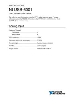
10 MinimumSR conductiontimeUCC24612-1245375475nsUCC24 612-2350540670nsAdaptiveMINIMUMOFF-TIMEt OFF_ABSMINA bsoluteminimumSR off-timeUCC24612-1200400595nsUCC24612-21 60360545tOFF_MAXM aximumSR sGATEDRIVERtr_VGVG rise time10%to 90%,CVG= nF103265nstf_VGVG fall time,90%to 10%,CVG= nF51635nsLIGHTLOAD/ ofstandbymode101520kHzfSTB_HYSA veragefrequencyhysteresisforstandbymode2 34kHzPROTECTIONTTSDT hermalshut-downthreshold130(1)165 CTHYST hermalshut-downrecoveryhysteresis15 CJunction Temperature (oC)Proportional Gate-drive Threshold (mV)-40-20020406080100120140-100-95-90-8 5-80-75-70-65-60-55-50-45-40-35D001 MeanMinimumMaximumJunction Temperature (oC)REG Pin Regulation Level VREG (V) = 0 mAILOAD_REG = 10 mAJunction Temperature (oC)SR Turn-off Threshold VTHVGOFF (mV) VDD12-V VDDJ unction Temperature (oC)SR Turn-on Threshold VTHVGON (mV)-40-20020406080100120140-500-450-400 -350-300-250-200-150-100-500D001 Junction Temperature (oC)UVLO Thresholds (V) ONUVLO OFFJ unction Temperature (oC)VDD Current, RUN (IVDDRUN) (mA) VDD12-V VDD24-V VDD8 UCC24612 SLUSCM5A AUGUST2017 2017 2018, UVLOT hresholdVoltagevs TemperatureFigure2.