Transcription of avalanche performance. - redrok.com
1 @ TC = 25 CContinuous Drain Current, VGS @ 10V169 ID @ TC = 100 CContinuous Drain Current, VGS @ 10V118 AIDMP ulsed Drain Current2 680PD @TC = 25 CPower Dissipation330 WLinear Derating CVGSGate-to-Source Voltage 20 VEASS ingle Pulse avalanche Energy 560mJIARA valanche CurrentSee , 12b, 15, 16 AEARR epetitive avalanche Energy mJdv/dtPeak Diode Recovery dv/dt Junction and-55 to + 175 TSTGS torage Temperature RangeSoldering Temperature, for 10 seconds300 ( from case ) CMounting Torque, 6-32 or M3 screw10 lbf in ( m)HEXFET power MOSFETS pecifically designed for Automotive applications, thisStripe Planar design of HEXFET power MOSFET sutilizes the latest processing techniques to achieveextremely low on-resistance per silicon area. Additionalfeatures of this HEXFET power MOSFET are a 175 Cjunction operating temperature, fast switching speedand improved repetitive avalanche rating.
2 These benefitscombine to make this design an extremely efficient andreliable device for use in Automotive applications and awide variety of other Maximum RatingsVDSS = 55 VRDS(on) = ID = 169A Process TechnologyOUltra Low On-ResistanceODynamic dv/dt RatingO175 C Operating TemperatureOFast SwitchingORepetitive avalanche Allowed up to TjmaxBenefitsAUTOMOTIVE MOSFETT hermal JCJunction-to-Case C/WR CSCase-to-Sink, Flat, Greased R JAJunction-to-Ambient 62TO-220 ABIRF1405 Typical ApplicationsOElectric power Steering (EPS)OAnti-lock Braking System (ABS)OWiper ControlOClimate ControlOPower Door hEWQWWIhs Typ. Max. Units ConditionsV(BR)DSSD rain-to-Source Breakdown Voltage55 VVGS = 0V, ID = 250 A V(BR)DSS/ TJBreakdown Voltage Temp. Coefficient V/ CReference to 25 C, ID = 1mARDS(on)Static Drain-to-Source On-Resistance VGS = 10V, ID = 101A VGS(th)Gate Threshold = 10V, ID = 250 AgfsForward Transconductance69 SVDS = 25V, ID = 110A 20 AVDS = 55V, VGS = 0V 250 VDS = 44V, VGS = 0V, TJ = 150 CGate-to-Source Forward Leakage 200 VGS = 20 VGate-to-Source Reverse Leakage -200nAVGS = -20 VQgTotal Gate Charge 170260ID = 101 AQgsGate-to-Source Charge 4466nCVDS = 44 VQgdGate-to-Drain ("Miller") Charge 6293 VGS = 10V td(on)Turn-On Delay Time 13 VDD = 38 VtrRise Time 190 ID = 101 Atd(off)Turn-Off Delay Time 130 RG = tfFall Time 110 VGS = 10V Between lead, 6mm ( )
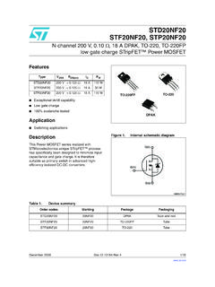
3 From packageand center of die contactCissInput Capacitance 5480 VGS = 0 VCossOutput Capacitance 1210 pFVDS = 25 VCrssReverse Transfer Capacitance 280 = , See Fig. 5 CossOutput Capacitance 5210 VGS = 0V, VDS = , = Capacitance 900 VGS = 0V, VDS = 44V, = Output Capacitance 1500 VGS = 0V, VDS = 0V to 44 VnHElectrical Characteristics @ TJ = 25 C (unless otherwise specified)LDInternal Drain InductanceLSInternal Source Inductance Leakage CurrentSDG ParameterMin. Typ. Max. Units ConditionsISContinuous Source CurrentMOSFET symbol(Body Diode) showing theISMP ulsed Source Currentintegral reverse(Body Diode) p-n junction Forward Voltage = 25 C, IS = 101A, VGS = 0V2 trrReverse Recovery Time 88130nsTJ = 25 C, IF = 101 AQrrReverse RecoveryCharge 250380nCdi/dt = 100A/ s2 tonForward Turn-On TimeIntrinsic turn-on time is negligible (turn-on is dominated by LS+LD)Source-Drain Ratings and Characteristics169 680e 2 Repetitive rating; pulse width limited by max.
4 Junction temperature. (See fig. 11). 2 Starting TJ = 25 C, L = RG = 25 , IAS = 101A. (See Figure 12). ISD 101A, di/dt 210A/ s, VDD V(BR)DSS, TJ 175 C Pulse width 400 s; duty cycle 2%.x X Coss eff. is a fixed capacitance that gives the same charging time as Coss while VDS is rising from 0 to 80% VDSS . 2 Calculated continuous current based on maximum allowable junction temperature. Package limitation current is 75A. 2 Limited by TJmax , see , 12b, 15, 16 for typical repetitive avalanche 4. Normalized On-ResistanceVs. TemperatureFig 2. Typical Output CharacteristicsFig 1. Typical Output CharacteristicsFig 3. Typical Transfer Characteristics 1 10 100 1 10 10020 s PULSE WIDTHT = 25CJ , Drain-to-Source Voltage (V)I , Drain-to-Source Current (A) 10 100 1 10 10020 s PULSE WIDTHT = 175CJ , Drain-to-Source Voltage (V)I , Drain-to-Source Current (A) 1 10 100 10004681012V = 25V20 s PULSE WIDTHDSV , Gate-to-Source Voltage (V)I , Drain-to-Source Current (A)GSDT = 25 CJ T = 175 CJ , Junction Temperature( C)R , Drain-to-Source On Resistance(Normalized)JDS(on) V=I=GSD10V169As 8.
5 Maximum Safe Operating AreaFig 6. Typical Gate Charge VoltageFig 5. Typical Capacitance VoltageFig 7. Typical Source-Drain DiodeForward Voltage060120180240300048121620Q , Total Gate Charge (nC)V , Gate-to-Source Voltage (V)GGSFOR TEST CIRCUITSEE FIGURE I=D13101AV= 27 VDSV= 44 VDS 1 10 100 ,Source-to-Drain Voltage (V)I , Reverse Drain Current (A)SDSDV = 0 V GST = 25 CJ T = 175 CJ 110100 VDS, Drain-to-Source Voltage (V)100100010000100000C, Capacitance(pF)CossCrssCissVGS = 0V, f = 1 MHZCiss = Cgs + Cgd, Cds SHORTEDCrss = Cgd Coss = Cds + Cgd01101001000 VDS , Drain-toSource Voltage (V)110100100010000ID, Drain-to-Source Current (A)Tc = 25 CTj = 175 CSingle Pulse1msec10msecOPERATION IN THIS AREA LIMITED BY RDS(on)100 secs 11.
6 Maximum Effective Transient Thermal Impedance, Junction-to-CaseFig 9. Maximum Drain Current TemperatureVDS90%10%VGStd(on)trtd(off)tf h 2 2 1 h 2p 2 % h q qhF F FIH +- hhFig 10a. Switching Time Test CircuitFig 10b. Switching Time :1. Duty factor D =t / t2. Peak T=Px Z+ T12 JDMthJCCPttDM12t , Rectangular Pulse Duration (sec)Thermal Response(Z ) = PULSE(THERMAL RESPONSE)2550751001251501750408012016020 0T , Case Temperature( C)I , Drain Current (A) CDLIMITED BY PACKAGEs F50K .2 F12 VCurrent RegulatorSame Type as Sampling Resistors+-IH2 Fig 13b. Gate Charge Test CircuitFig 13a. Basic Gate Charge WaveformFig 12c. Maximum avalanche EnergyVs. Drain CurrentFig 12b. Unclamped Inductive WaveformsFig 12a. Unclamped Inductive Test CircuittpV(BR) +-VDDDRIVERA15V20 VFig 14.
7 Threshold Voltage Vs. Temperature-75-50-250255075100125150175T J , Temperature ( C ) (th) , Variace ( V )ID = 250 A255075100125150175020040060080010001200 Starting T , Junction Temperature( C)E , Single Pulse avalanche Energy (mJ)JAS IDTOPBOTTOM41A 71A 101A s 15. Typical avalanche Current 16. Maximum avalanche EnergyVs. TemperatureNotes on Repetitive avalanche Curves , Figures 15, 16:(For further info, see AN-1005 at )1. avalanche failures assumption: Purely a thermal phenomenon and failure occurs at a temperature far in excess of Tjmax. This is validated for every part Safe operation in avalanche is allowed as long asTjmax is not Equation below based on circuit and waveforms shown in Figures 12a, PD (ave) = Average power dissipation per single avalanche BV = Rated breakdown voltage ( factor accounts for voltage increase during avalanche ).
8 6. Iav = Allowable avalanche T = Allowable rise in junction temperature, not to exceed Tjmax (assumed as 25 C in Figure 15, 16). tav = Average time in avalanche . D = Duty cycle in avalanche = tav f ZthJC(D, tav) = Transient thermal resistance, see figure 11)PD (ave) = 1/2 ( BV Iav) =2hT/ ZthJCIav = 2hT/ [ BV Zth]EAS (AR) = PD (ave) (sec)1101001000 avalanche Current (A) Cycle = Single avalanche Current vs avalanche pulsewidth, tav assuming Tj = 25 C due to avalanche TJ , Junction Temperature ( C)0100200300400500600 EAR , avalanche Energy (mJ)TOP Single Pulse BOTTOM 10% Duty CycleID = 101As 2h 2 2 G 2 2g Recoverydv/dtRipple 5%Body Diode Forward DropRe-AppliedVoltageReverseRecoveryCurr entBody Diode ForwardCurrentVGS=10 VVDDISDD river Gate VDSW aveformInductor CurentD = P.
9 W .Period+-+++--- q hh G 2 2 2 q s h2 2 2h 2p 24h4 hF F F2E2h 2 2 ! hF F Bg 2v 2g ! ! 2v $2 2s 22 q 2 22 v $2v ( ) 2s 222222g 2 !* + B22 ! 2 2 *2hF F 2* 2 Eg, q 2222 2222 BBB2 q 2a2 SFH 2* 2v ) 2v 2 2Q 2h 2h ! 2222222222 2 BBBp 2 IUF2 For N-channel2 HEXFET power MOSFETss and specifications subject to change without notice. This product has been designed and qualified for the Automotive [Q101] Standards can be found on IR s Web WORLD HEADQUARTERS: 233 Kansas St., El Segundo, California 90245, USA Tel: (310) 252-7105 TAC Fax: (310) 252-7903 Visit us at for sales contact information. 12/04 yEPPHef2 2y 22@h 2 2 2 2 2@ AA yEPPHef2 2w 2s EXAMPLE:IN THE ASSEMBLY LINE "C"T HIS IS AN IRF 1010 L OT CODE 1789AS S E MB L E D ON WW 19, 1997 PART NUMBERASSEMBLYLOT CODEDAT E CODEYE AR 7 = 1997 LINE CWE E K 19 LOGOR E CT IF IE RINT E R NAT IONALNote: "P" in assembly lineposition indicates "Lead-Free"TO-220AB packages are not recommended for Surface Mount : For the most current drawings please refer to the IR website at.