Transcription of AXE033 SERIAL I2C LCD - Home - PICAXE
1 AXE033 SERIAL /I2C LCDThe SERIAL LCD and clock module allows microcontroller systems ( PICAXE ) tovisually output user instructions or readings, without the need for a computer. Thisis especially useful when working, for example, with analogue sensors, as theanalogue reading can easily be displayed on the LCD module. All LCD commandsare transmitted serially via a single microcontroller pin using the serout print the text Hello the command is simply:serout ,N2400,( Hello )The module can also store 7 programmable pre-defined messages to save memoryspace usage within the PICAXE optional low-cost clock upgrade provides a real-time clock and programmablealarm output.
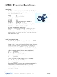
2 The LCD can show the current date and time on it s display, and thealarm output can be programmed to trigger at any period between 10 seconds and 1year. The clock has a lithium coin cell backup that maintains the time for up to tenyears when the main power supply is Features:1. 16x2 LCD Alphanumeric Display2. Simple SERIAL (1 wire) connection to microcontroller (2400,N,8,1).3. Optional i2c 7 Programmable pre-defined messages5. Small footprint (almost same size as the LCD).6. Optional low-cost clock upgrade, providing Real Time Clock Programmable Alarm Output 1Hz pulse output 10 year battery backuprevolution copyright 2003-12 Revolution Education : the full datasheet please LCD AND CLOCK revolution copyright 2003-12 Revolution Education : Mode?
3 ( SERIAL or i2c)Most users will use the module in the default SERIAL only main reason to use it in i2c mode is if you wish to read the time/data fromthe DS1307 clock upgrade directly into the PICAXE all othe cases the SERIAL mode should be i2c mode the LCD module acts as a dumb i2c slave device. The clock and alarmfunctions are not available - all clock and alarm functions must be carried out bythe PICAXE part Section 1 for construction and assembly details. A jumper link (J1) is requiredfor i2c Section 2 on pages 6-7 for i2c connection details and samples. Furtherinformation about i2c protocol and interfacing can be found in the i2c Tutorial help file.
4 It is assumed that the user has already read this help Section 3 on pages 8-15 for SERIAL connection details and LCD AND CLOCK revolution copyright 2003-12 Revolution Education : 1 - Construction and Kit Contents pre-populated PCB 16x2 alphanumeric display (brand may vary) bag of 4 support posts and 3x 10 pin headers 5R6 and 0 ohm resistors (backlit LCD display AXE033B only)The LCD is supplied loose so that it can be either fitted directly to theboard, or connected via a longer ribbon cable connection if following instructions explain how to fit the LCD directly to theboard (track side) and presume the user is confident at the LCD1. Snap one header into a 4 and 6 way (LCD) or AXE033Y (OLED)Place the short end of the 4 way section, with another 10 way header,through the holes labelled 1-14 on the pcb (from the track side of the PCB, sothat the top of the short end shows on the component side).
5 Note the extraholes marked A and K and resistor RB are only used on LCDs with LEDbacklights (the LCD in the kit does not have a backlight and so theseconnections are not required).AXE033B (LCD with backlight)Place the short end of the 6 way section, with another 10 way header, throughthe holes labelled 1-16 (or 1-14,A,K) on the pcb (from the track side of thePCB, so that the top of the short end shows on the component side).Solder a resistor in the position RB. The value of the resistor depends on thepower supply - for use the zero ohm (single black band) resistor, for 5V usethe ohm Carefully solder each header pin (on the component side of the pcb).
6 Check each joint carefully for shorts between Solder a wire link in position J2 (power) if a battery pack is to be is not required for a 5V or 6V Solder a wire link in position J1 (mode) if the LCD is to be used in i2c link is required for the default SERIAL Click the four support posts onto the PCB. They are designed to be a tight fit!6. Carefully click the LCD over the header pins and onto the support posts;.7. Solder the LCD to the pin Snap the 6 pin header into a 2 and 4 way section. Solder the two way section tothe CLK contacts on the Connect a power supply to the main connection header (red wire to V+, blackwire to 0V). The LCD should display a time message when the two CLKcontacts are shorted ( with the jumper provided in the kit) and once thecontrast is adjusted (via the variable resistor marked contrast ).
7 If the LCDdoes not display a message check the power, contrast and the 14 connector pinscarefully. (Note that if the optional clock upgrade chip is not fitted, the timewill always show as 00/00/00 00:00)See page 8 for a sample PICAXE SERIAL test that the LCD is fittedabove the TRACK side of thePCB. Ensure no solder bridgesbetween pins on the LCD AND CLOCK revolution copyright 2003-12 Revolution Education : the Optional Clock UpdateRequired: CR2032 lithium coin cell DS1307 Clock ICInstructions:1. Place the DS1307 into the 8 pin socket, ensuring pin 1 is facing the lithium Place the CR2032 lithium coin cell in the holder, ensuring the positive (+) sideis facing :Note that the lithium coin cell keeps the DS1307 clock operating when the mainpower supply is not connected.
8 This ensures accurate time is kept by the coin cell does not power the LCD or the pulse output. The coin cell will lastapproximately 10 that the clock and alarms (and pulse output) will not operate correctly untilthe initial time is programmed into the module (see the Programming Time intothe Module section below).Users in USAP lease note that the date convention used in the module is the UK date formatdd/ coin cell5 SERIAL / i2c lcd AND CLOCK revolution copyright 2003-12 Revolution Education : / Output / Power ConnectionsMain Header (V+,0V)The main header provides connection for thepower supply (5-6V DC on V+). If you wish touse solder a wire link in position J2(power).
9 This shorts out the voltage protectiondiode D1, as this diode causes a voltagedrop, which can make the screen very dim atthis lower header (IN)These is the SERIAL input (IN).Main header (SDA and SCL)These are the i2c mode connections. They must only be used when a wire link hasbeen soldered in position J1 to put the module into i2c mode (see section 2).Main header (OUT)The alarm output triggers (goes high for 5 seconds) whenever a clock alarm alarm output can sink or source Output (PLS)The pulse output outputs a square wave of 1Hz (1 pulse per second) when theoptional DS1307 clock IC is fitted. A 330R resistor is included on the board toallow a low current LED to be soldered directly to this connection to provide aflashing second indicator.
10 The pulse output can sink or source 20mA. The pulseoutput will not operate until the clock upgrade is fitted and the correct time isprogrammed into the Jumper (CLK)When the clock jumper is fitted the module goes into clock mode. During thismode instructions cannot be sent via the SERIAL connection, as the unit is acting as astandalone alarm clock . User defined message 1 is constantly shown on the topline of the LCD and the time is constantly shown on the bottom line of the LCD(when the module is powered). The pulse output and alarm output operate Backlight (LCD) - Only used with backlit kit AXE033 BWhen a backlight is fitted the LCD connection allows power to be applied to thebacklight.