Transcription of BPSK - BINARY PHASE SHIFT KEYING
1 BPSK - BINARY PHASE SHIFT keyingVol D1, ch 8, rev - 69 BPSK - BINARY PHASEBPSK - BINARY PHASEBPSK - BINARY PHASEBPSK - BINARY PHASESHIFT KEYINGSHIFT KEYINGSHIFT KEYINGSHIFT 70generation of 70bandlimiting .. 71 BPSK 72phase .. 73the BPSK generator .. 73 BPSK 74measurements .. 75further study .. 76 TUTORIAL QUESTIONS .. 7870 - D1 BPSK - BINARY PHASE SHIFT keyingBPSK - BINARY PHASEBPSK - BINARY PHASEBPSK - BINARY PHASEBPSK - BINARY PHASESHIFT KEYINGSHIFT KEYINGSHIFT KEYINGSHIFT KEYINGACHIEVEMENTS: generation of BINARY PHASE SHIFT keyed (BPSK) signal;bandlimiting; synchronous demodulation - PHASE : it would be advantageous to have completed some of theexperiments in Volume A1, involving linear modulation anddemodulation.
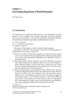
2 Familiarity with the DECISION MAKER, LINE-CODE ENCODER and LINE-CODE DECODER modules is MODULES: DECISION MAKER, LINE-CODE ENCODER and LINE-CODE DECODER. A total of two PHASE SHIFTER modules of BPSK generation of BPSK generation of BPSK generation of BPSKC onsider a sinusoidal carrier. If it is modulated by a bi-polar bit stream according tothe scheme illustrated in Figure 1 below, its polarity will be reversed every time thebit stream changes polarity. This, for a sinewave, is equivalent to a PHASE reversal( SHIFT ).
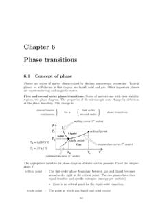
3 The multiplier output is a BPSK 1 bi-polar bit stream carrier ( ) (centred on ) 0 +V -V T T = bit clock period 2 T Figure 1: generation of BPSK 1 also sometimes called PRK - PHASE reversal - BINARY PHASE SHIFT keyingD1 - 71 The information about the bit stream is contained in the changes of PHASE of thetransmitted synchronous demodulator would be sensitive to these PHASE appearance of a BPSK signal in the time domain is shown in Figure 2 (lowertrace).
4 The upper trace is the BINARY message Figure 2: a BPSK signal in the time is something special about the waveform of Figure 2. The wave shape is symmetrical at each PHASE transition . This is because the bit rate is a sub-multipleof the carrier frequency /(2 ). In addition, the message transitions have been timedto occur at a zero-crossing of the this is referred to as special , it is not uncommon in practice. It offers theadvantage of simplifying the bit clock recovery from a received signal.
5 Once thecarrier has been acquired then the bit clock can be derived by what does it do to the bandwidth ?See Tutorial Question basic BPSK generated by the simplified arrangement illustrated in Figure 1 willhave a bandwidth in excess of that considered acceptable for you can calculate the spectrum of the BINARY sequence then you know thebandwidth of the BPSK itself. The BPSK signal is a linearly modulated DSB, andso it has a bandwidth twice that of the baseband data signal from which it isderived practice there would need to be some form of bandwidth can be performed either at baseband or at carrier frequency.
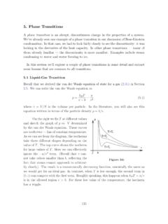
6 It will beperformed at baseband in this experiment. 2 this assumes > 2B72 - D1 BPSK - BINARY PHASE SHIFT keyingBPSK demodulationBPSK demodulationBPSK demodulationBPSK demodulationDemodulation of a BPSK signal can be considered a two-stage translation back to baseband, with recovery of the bandlimited messagewaveform2. regeneration from the bandlimited waveform back to the BINARY message back to baseband requires a local, synchronized 1stage 1stage 1stage 1 Translation back to baseband is achieved with a synchronous demodulator, as shownin Figure 3 requires a local synchronous carrier.
7 In this experiment a stolen carrier will acquisition will be investigated in the experiment entitled DPSK - carrieracquisition and BER (within Volume D2 - Further & Advanced Digital Experiments)BPSK ( )( )( )( ) (centred on ) stage 1 stage 2 bit clock carrier DETECTOR Figure 3: synchronous demodulation of BPSK stage 2stage 2stage 2stage 2 The translation process does not reproduce the original BINARY sequence, but abandlimited version of original BINARY sequence can be regenerated with a detector.
8 This requiresinformation regarding the bit clock rate. If the bit rate is a sub-multiple of the carrierfrequency then bit clock regeneration is TIMS the DECISION MAKER module can be used for the regenerator, and inthis experiment the bit clock will be a sub-multiple of the ambiguityphase ambiguityphase ambiguityphase ambiguityYou will see in the experiment that the sign of the PHASE of the demodulator carrier ambiguity is a problem in the demodulation of a BPSK are techniques available to overcome this.
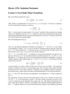
9 One such sends a trainingsequence, of known format, to enable the receiver to select the desired PHASE ,BPSK - BINARY PHASE SHIFT keyingD1 - 73following which the training sequence is replaced by the normal data (untilsynchronism is lost !).An alternative technique is to use differential encoding. This will be demonstrated inthis experiment by selecting a different code from the LINE-CODE BPSK generatorthe BPSK generatorthe BPSK generatorthe BPSK generatorThe BPSK generator of Figure 1 is shown in expanded form in Figure 4, andmodelled in Figure 5 PRBS clk data TTL sine BPSK DIGITAL DIVIDE by 4 Figure 4: block diagram of BPSK generator to be modelledNote that the carrier will be four times the bit clock lowpass filter is included as a band limiter if required.
10 Alternatively a bandpassfilter could have been inserted at the output of the generator. Being a linear system,the effect would be the - D1 BPSK - BINARY PHASE SHIFT keyingBPSK ext trig 8 kHz Figure 5: model of the BPSK generatorThe AUDIO OSCILLATOR supplies a TTL signal for the bit clock digital DIVIDE-BY-FOUR sub-system in the LINE-CODE ENCODER, and a sinusoidal signal for PHASE SHIFTER (set to the LO range with the on-board switch SW1) allowsrelative PHASE shifts. Watch the PHASE transitions in the BPSK output signal as thisphase is altered.