Search results with tag "Nand gates"

Experiment 1 - Basic Logic Gates
mems.ece.dal.caExperiment 1 - Basic Logic Gates Objectives: 1. To study the truth tables of various basic logic gates 2. To verify DeMorgan’s Theorem 3. To implement an INVERTER using NAND or NOR gates 4. To implement an OR gate using NAND gates Note: There is no lab report required for this lab. Fill out the observation sheets,

The basic logic gates arethe inverter (or NOT gate), the ...
www.ee.ic.ac.ukNAND gate, we can build the three basic logic operators: NOT, AND and OR. As a result, we can build ANY logic circuit and implement any Boolean expression. Taken to limit, give me as many NAND gate as I want, in theory I can build a Pentium processor. This shows the universality of the NAND gate. Similarly, one can do the same for NOR gates.

LOGIC GATES (PRACTICE PROBLEMS) - Free GATE ECE 2017 ...
www.gatestudy.comNAND gate satisfies the condition but EX-OR gates does not as it gives 0 output for the same inputs. Option (b) is the correct choice where both gates satisfy the given condition. 3. A locker has been rented in the bank. Express the process of opening the locker in
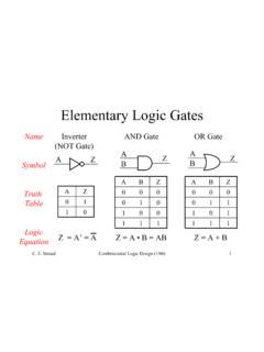
Elementary Logic Gates - Auburn University
eng.auburn.edu• The NAND gate is functionally complete ¾We can build any digital logic circuit out of all NAND gates • Same holds true for the NOR gate and the multiplexer • The XOR & XNOR are not functionally complete Z=AB A B Z=A+B using DeMorgan’s Theorem A B

MC14001B - B-Suffix Series CMOS Gates
www.onsemi.comMC14001B Quad 2−Input NOR Gate MC14011B Quad 2−Input NAND Gate MC14023B Triple 3−Input NAND Gate MC14025B Triple 3−Input NOR Gate MC14071B Quad 2−Input OR Gate MARKING DIAGRAMS SOIC−14 D SUFFIX CASE 751A TSSOP−14 DT SUFFIX CASE 948G 1 14 140xxBG AWLYWW 14 0xxB ALYW 1 14 xx = Specific Device Code A = Assembly Location …

Integrated Circuit Basics - Electronics
cie-wc.eduDec 20, 2011 · Gate, OR Gate, NAND Gate, NOR Gate and the NOT Gate which is also known as an Inverter. You may also hear about Buffers in future lessons. Pinout Diagrams ... •The next two diagrams are both Quad Two-input NOR Gates. –The difference is that one is a TTL and the other is a CMOS IC. –Look at the difference in the Pinout Diagrams.
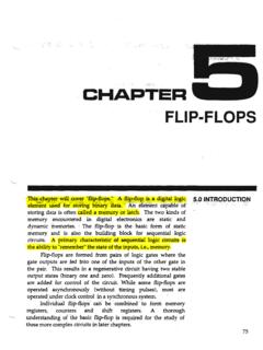
FLIP-FLOPS
www.csun.eduNAND gates to the simple 5-C flip-flop as shown in Figure 5-,.8: Set . a . Clock · a . Clear . Notice that this circuit only provides clock control of the S ...
Module 5 Logic Diagrams - NTC Sites
sites.ntc.doe.govNOT gate - provides a reversal of the input. If the input is on, the output will be off. If the input is off, the output will be on. Because the NOT gate is frequently used in conjunction with AND and OR gates, special symbols have been developed to represent these combinations. The combination of an AND gate and a NOT gate is called a NAND gate.

NAND & NOR Implementation - Digital Logic Design (EEE 241)
digitallogicdesign.weebly.comUniversal Gate –NAND I will demonstrate •The basic function of the NAND gate. •How a NAND gate can be used to replace an AND gate, an OR gate, or an INVERTER gate. •How a logic circuit implemented with AOI logic gates can be re-implemented using only NAND gates. •That using a single gate type, in this case NAND, will reduce the number of integrated circuits (IC) …
Digital Phase Locked Loop - University of Maine
ece.umaine.edu3.1.2 2 Input NAND Figure 3 shows a common 2 input CMOS nand gate. A 2:1 overall well width ratio (see Inverter) was employed. 3.1.3 3 Input NAND Figure 4 shows a common 3 input CMOS nand gate. A 2:1 overall well width ratio (see Inverter) was employed. 3.1.4 8 Input NAND Figure 5 shows a common 8 input CMOS nand gate.

Quad 2-input NAND gate - Nexperia
assets.nexperia.comQuad 2-input NAND gate Rev. 9 — 22 October 2021 Product data sheet 1. General description The 74HC00; 74HCT00 is a quad 2-input NAND gate. Inputs include clamp diodes. This enables the use of current limiting resistors to interface inputs to voltages in excess of VCC. 2. Features and benefits • Wide supply voltage range from 2.0 to 6.0 V

EXPERIMENT 3: TTL AND CMOS CHARACTERISTICS
www.classe.cornell.eduConsider the NAND gate in Figure 3.4, connected as a NOT gate. The input waveform, Vin, is a non-ideal pulse. When the input signal goes HIGH, the output will go LOW after the turn-on delay time tPHL. The figure illustrates the turn-on delay for a non-ideal output pulse. The typical turn-on delay for a standard series TTL NAND gate is 7 ns.

LADDER LOGIC - Sharif
ee.sharif.eduFrom the switches to the coil of CR1, the logical function is that of a NAND gate. CR1's normally-closed contact provides one final inversion to turn the NAND function into an AND function. • REVIEW: • Parallel contacts are logically equivalent to an OR gate. • Series contacts are logically equivalent to an AND gate.

Digital Electronics Lab - brcmcet.edu.in
www.brcmcet.edu.in1. 3 I/P NAND GATE IC 7410 2 2. OR GATE IC 7432 3 3. NOT GATE IC 7404 1 2. IC TRAINER KIT - 1 3. PATCH CORDS - 27 THEORY: ENCODER: An encoder is a digital circuit that performs inverse operation of a decoder. An encoder has 2n input lines and n output lines. In encoder the output lines generates the binary code n