Example: air traffic controller
Elementary Logic Gates - Auburn University
• The NAND gate is functionally complete ¾We can build any digital logic circuit out of all NAND gates • Same holds true for the NOR gate and the multiplexer • The XOR & XNOR are not functionally complete Z=AB A B Z=A+B using DeMorgan’s Theorem A B
Tags:
Information
Domain:
Source:
Link to this page:
Documents from same domain

Daniel W. Mackowski - Auburn University
eng.auburn.edu1.1.1 Fourier’s Law and the thermal conductivity Before getting into further details, a review of some of the physics of heat transfer is in order. As you recall from undergraduate heat transfer, there are three basic modes of transferring heat: conduction, radiation, and convection. Conduction is the transfer of heat through a medium
Chapter 2 Governing Equations of Fluid Dynamics
eng.auburn.eduGoverning Equations of Fluid Dynamics J.D. Anderson, Jr. 2.1 Introduction The cornerstone of computational fluid dynamics is the fundamental governing equations of fluid dynamics—the continuity, momentum and energy equations. These equations speak physics. They are the mathematical statements of three fun-damental physical principles upon ...
BPSK - BINARY PHASE SHIFT KEYING
eng.auburn.eduThe PHASE SHIFTER (set to the LO range with the on-board switch SW1) allows relative phase shifts. Watch the phase transitions in the BPSK output signal as this phase is altered. This PHASE SHIFTER can be considered optional. The digital DIVIDE-BY-FOUR sub-system within the LINE-CODE ENCODER is used

Karnaugh Maps (K-map) - Auburn University
eng.auburn.eduC. E. Stroud Combinational Logic Minimization (9/12) 2 Karnaugh Maps (K-map) • Alternate forms of 3-variable K-maps Note end-around adjacency
Related documents

Quad 2-input NAND gate - Nexperia
assets.nexperia.comQuad 2-input NAND gate Rev. 9 — 22 October 2021 Product data sheet 1. General description The 74HC00; 74HCT00 is a quad 2-input NAND gate. Inputs include clamp diodes. This enables the use of current limiting resistors to interface inputs to voltages in excess of VCC. 2. Features and benefits • Wide supply voltage range from 2.0 to 6.0 V

DESIGNING COMBINATIONAL LOGIC GATES IN CMOS
bwrcs.eecs.berkeley.eduExample 6.1 Two input NAND Gate Figure 6.5 shows atwo-input NAND gate F = A·B(). The PDN network consists of two NMOS devices in series that conduct when both A and B are high. The PUN is the dual net-work, and consists of two parallel PMOS transistors. This means that F is 1 if A = 0 or B = 0, which is equivalent to F = A·B. The truth table ...

Combinational Logic Gates in CMOS
engineering.purdue.edu3-Input NAND gate with Parasitic Capacitors in c out in b in a C p+load C a C b C c P1 P2 P3 R n=0.5R p= C a=C b=C c=C j=0.05pF C p=3C j=0.15pF C load=2C g=0.20pF 2 10 4 1
Module 5 Logic Diagrams - NTC Sites
sites.ntc.doe.govNOT gate - provides a reversal of the input. If the input is on, the output will be off. If the input is off, the output will be on. Because the NOT gate is frequently used in conjunction with AND and OR gates, special symbols have been developed to represent these combinations. The combination of an AND gate and a NOT gate is called a NAND gate.

LADDER LOGIC - Sharif
ee.sharif.eduIf we take our OR function and invert each "input" through the use of normally-closed contacts, we will end up with a NAND function. In a special branch of mathematics known as Boolean algebra, this effect of gate function identity changing with the inversion of input signals is described by DeMorgan's Theorem, a subject to be explored
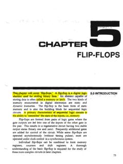
FLIP-FLOPS - California State University, Northridge
www.csun.edusingle OR gate. The circuit is constructed by feeding the ,gate output back into one of the gate inputS as'showrfinFigute'5-l. ' FIGURE 5-1. OR Gate Latch. , , , When,. the:.. circuit . ou~tisin ·the LO state and the latch command input isLO "the lat91 will ,have it's qutpllt ' r~mail1 low. When the latch command 'in'putis forced ffi~ the gate

Logic Gates - BU
www.bu.eduan input of 5 or 6 –all of the information need to be 0s and 1s • Reminder: Input refers to the information you give the logic gate, and output refers to what it spits out! • Let’s try this example again, keeping this rule in mind! 1 (ON) Logic Gate 1 (ON) 1 (ON) 0 …

6.1 Sum-of-Products - East Tennessee State University
faculty.etsu.edumore AND gates. The outputs from these gates are all input to a single OR gate. Figure 6-1 shows a sample SOP binary circuit. Figure 6-1 Sample Sum-of-Products Binary Circuit 6.2 Converting an SOP Expression to a Truth Table Examining the truth table for an AND gate reveals that exactly one row has a one for its output.