Transcription of Bulletin D-57 D-57:D-57 7/10/09 10:39 AM Page 1 Model 1430 ...
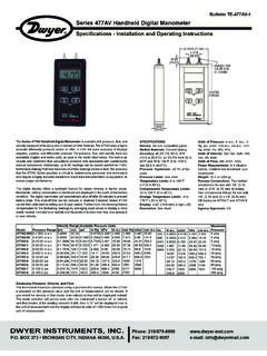
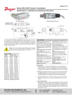
1 D-57:D-57 7/10/09 10:39 AM Page 1. Bulletin D-57. Model 1430 microtector Electronic Point Gage Installation and Operating Instructions Model 1430 microtector Portable Three-point mounting, dual leveling Electronic Point Gage combines mod- adjustment, and circular level vial ern, solid-state integrated circuit elec- assure rapid setup tronics with a time-proven point gage Durablock precision-machined acrylic manometer to provide fast, accurate plastic gage body pressure measurements. Sensitive 0 - 50 microamp meter acts as a detector and also indicates battery and probe condition SPECIFICATIONS AND FEATURES *. Heavy 2 thick steel base plate Accurate and repeatable to .00025 provides steady mounting inches water column Top-quality glass epoxy circuit board Pressure range: 0 - 2 , positive, and solid-state, integrated circuit negative, or differential pressures electronics Non-toxic and inexpensive gage fluid Electronic enclosure of tough, molded consists of distilled water mixed with styrene acrylonitrile provides maximum a small amount of fluorescein green protection to components yet allows color concentrate easy access to battery compartment Convenient, portable, lightweight Rugged sheet steel cover and carrying and self-contained, the unit requires case protects the entire unit when not no external power connections and in use is operated by a volt penlight cell Accessories included are (2) 3-foot detector current eliminates lengths Tygon tubing, (2) 1/8 pipe point plating, fouling and erosion thread adapters and 3/4 oz.
2 Bottle of Micrometers are manufactured in accor- fluorescein green color concentrate dance with ASME , and with wetting agent are traceable to a standard at the National Maximum pressure: 100 psig with Institute of Standards and Technology optional pipe thread connections. Tygon is a registered trademark of Saint-Gobain Corporation DWYER INSTRUMENTS, INC. Phone: 219/879-8000 BOX 373 Fax: 219/872-9057 e-mail: MICHIGAN CITY, INDIANA 46361, D-57:D-57 7/10/09 10:39 AM Page 2. OFF ON. LOW. PRESSURE. FLUID. LEVEL. microtector Gage Precision Pressure Measurement On indication of contact, the operator stops The microtector Gage combines the time- lowering the point and reads the micrometer proven principles of the Hook Gage type which indicates one half the applied pressure. manometer and modern solid-state integrat- By interpolating eight divisions (each being ed circuit electronics.)
3 It provides an inexpen- .000125 ) between .001 micrometer sive means of achieving accuracy and graduations, a total accuracy of .00025 can repeatability within .00025 inches water col- easily be achieved. The micrometer complies umn throughout its 0 to 2 inches range. with Federal Specification GGG-C-105A and It is truly a new standard in precision measur- is traceable to a master at the NIST. ing devices. Locating and Opening Principles of Operation Stand the microtector Gage and case on a A pressure to be measured is applied to the firm flat level surface. Remove cover by manometer fluid which is displaced in each releasing the latches and lifting it straight up. leg of the manometer by an amount equal to If it is necessary to move the gage without 1/2 the applied pressure. A micrometer case, handle only the base plate or clear mounted point is then lowered until it contacts acrylic block.
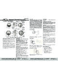
4 (CAUTION: Do not handle gage the manometer gage fluid. The instant of con- by grasping meter-electronic package hous- tact is detected by completion of a low-power ing Item 7 on drawing.). circuit. Current for this circuit is supplied by a volt penlight cell feeding two semi- conductor amplifiers which act as a free-run- ning multivibrator operating at a frequency of approximately two kilohertz. Completion of the circuit activates a bridge rectifier which provides the signal for indication on a sensitive (0 to 50 microamps) microam- meter. 2. D-57:D-57 7/10/09 10:39 AM Page 3. Fluid Level After making contact, turn the point out of the Level the gage by adjusting the two front lev- fluid by turning the micrometer barrel counter- eling screws (Item 8 on drawing) until the bub- clockwise to a reading of .010 or more. Again, ble in the spirit level is centered in the small watch the meter and, this time, lower the circle.
5 After leveling the gage, open both rapid point by turning the micrometer barrel. The shut-off valve tube connectors (Items 2 and point position where the meter pointer begins 5). Back off the micrometer (Item 4), if neces- to move up scale is the zero position. This sary, to make sure that the point is not position should correspond to the zero read- immersed in the gage fluid. The fluid level in ing on the micrometer. Adjust the point in rela- the gage should now coincide with the mark tion to the micrometer barrel by turning the on the right hand bore (Item 6) plus or minus top knob while holding the barrel steady. approximately 1/32 inch. If the level of fluid is Repeat lowering the point, watching the too high, fluid can be removed with an eye meter for contact, and adjusting the point dropper pipette or carefully poured out of the until the zero position and zero reading exact- right connection (Item 5).
6 Ly coincide. The gage is now zeroed and should not be moved. If the level is too low, remove the top left rapid shut-off valve tube connector (Item 2) and An alternative method of zeroing and reading add distilled water pre-mixed with the proper can be used wherein, instead of zeroing the amount of green concentrate. (See mainte- gage completely, a zero correction reading is nance instructions for proportions. After cor- taken and recorded, then subtracted from the recting the fluid level, re-install the rapid shut- final reading. Comparable results can be off connectors and, with these in the open obtained with either method. position, re-level the microtector Gage. The gage is now ready to be zeroed. Positive Pressure Measurement With the fluid at its proper level, a pressure of water column maximum can be meas- Zeroing ured. Positive pressure should be applied to Turn the Micrometer barrel (Item 4) until its the top left connection (Item 2) with the lower end just coincides with the zero mark micrometer zeroed as described above.)
7 This on the scale and the zero on the barrel scale will permit a simple direct reading to be taken. coincides with the vertical line on the internal scale. Note that the internal scale is graduat- After an unknown pressure has been applied ed every .025 from 0 to inch and the at the top left connection, the fluid level will barrel scale is graduated in one thousandths drop in the left bore and rise over the point in from 0 to .025 . Turn the meter circuit switch the right bore. Note that the indicating meter at the top of gage to the on position. While point has moved upscale because the point is holding the barrel at the zero position (and immersed in the fluid. Turn the micrometer with gage level), raise or lower the point by counter-clockwise until the point leaves the turning the knurled knob (Item 3) until the fluid as indicated by the meter pointer drop- point is above, but near, the fluid.
8 Ping to zero on its scale. Then slowly turn the micrometer down until its point just touches Check to be sure that the meter registers the fluid surface, causing movement of the zero. Watch the meter, hold the barrel, and meter pointer. Withdraw the point and repeat lower the point slowly by turning the top several times, noting each time the microme- knurled knob. As the knob is turned, the point ter reading where the meter pointer begins. will contact the fluid and the meter pointer will The average of these readings multiplied by move from zero to some upscale position. two is the pressure applied to the gage. (Avg. reading x 2 = pressure applied in inches The degree of uncertainty for the operator is indicated by the difference in these readings. 3. D-57:D-57 7/10/09 10:39 AM Page 4. When the readings are complete, the pres- (2) If the meter operation continues to be sure should be removed and the zero setting sluggish, replace the size AA, volt battery.)
9 Of microtector Gage rechecked. Any change (Replace the battery at least once a year to in the zero position will indicate inaccurate avoid deterioration of battery and damage to readings. Should this happen, the zero-set gage. Leakproof alkaline battery is recom- and pressure measurement procedure should mended.). be repeated. To replace the battery, remove center screw Negative Pressure (Item 10) located in the back of the electronic or Vacuum Measurement enclosure. Cover (Item 9) will come off, Zero the gage. Connect the source of vacu- exposing the battery. Pull the old battery out um or negative pressure to the right-side and push a new battery into the battery hold- gage connection (Item 5) and proceed as er with the positive (center) terminal to the described under Positive Pressure right (to the end marked with + on the holder). Measurement section. Remember that the pressure measured in this way is negative.
10 If the fluid becomes contaminated and requires replacement: empty old fluid from Differential Pressure Measurement gage; flush out with clear water and replace Differential pressures may be measured by with distilled water and A-126 fluorescein connecting the higher (more positive) pres- green color concentrate mixed with 3/4 oz. sure to the left connection (Item 2) and the concentrate to each quart of water. lower pressure to the right connection (Item 5). CAUTION: 1. Do not substitute other gage fluids, as Storage proper gage operation depends on use of the Turn meter circuit switch to off position and specified gage fluid to provide proper surface withdraw the point well clear of fluid (by turn- tension, wetting ability and electrolyte capa- ing micrometer clockwise) when gage is not in bility with unity specific gravity. use. This will conserve the batteries and min- imize build-up of oxides, etc.