Transcription of Bulletin E-51 Series 1620 – Single and Dual Pressure Switches
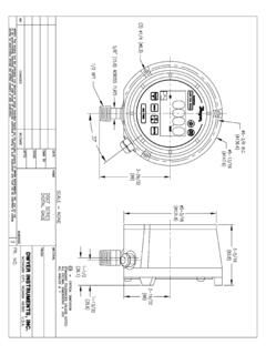
1 Bulletin E-51. Series 1620 Single and dual Pressure Switches . Specifications - Installation and Operating Instructions 8-7/8. [ ]. 2X 9/32 [ ] 7-3/4. MOUNTING HOLE [ ] 8-1/4. [ ]. 1-1/2. [ ]. 7/8 [ ] 5-15/64. OPENING FOR 1/2 [ ]. CONDUIT. CONNECTION. 2X 45 . 2X R4-5/16. 11/16 [ ] [ ] 1/8 FEMALE NPT. 1-17/64 [ ] 1/8 FEMALE HIGH Pressure . 3-1/64 NPT LOW Pressure CONNECTION. [ ] 3 CONNECTION. Series 1620 Pressure switch [ ]. 4-9/32 [ ]. INSTALLATION SPECIFICATIONS. 1. switch is normally calibrated for mounting in the vertical position with Pressure Service: Air and non-combustible, Electrical Connections: 3 screw type, and electrical connections pointing down. If other mounting is desired, it should be compatible gases. common, normally open and normally specified when ordering. Wetted Materials: Consult factory. closed. 2. Two lugs with 9/32 diameter holes, 180 degrees apart on an 8-1/4 diameter circle Temperature Limits: -30 to 130 F Process Connections: 1/8 female NPT.
2 Are provided. ( to C). Mounting Orientation: Diaphragm in 3. The location selected should be free from excessive vibration and ambient Pressure Limits: Max. 50 in. ( vertical position. Consult factory for other temperatures should not be above 130 . kPa) continuous, 2 psig ( kPa) position orientations. surge. Set Point Adjustment: Screw OPERATION switch Type: 1626, Single -pole double- Adjustment. 1. General Differential Pressure acting on the power diaphragm rotates a channel, throw (SPDT); 1627, two Single -pole Weight: Model 1626, 3 Ib, oz ( compressing a calibrated spring. The rotation of the channel actuates a snap switch double-throw (SPDT) . kg); Model 1627, 3 Ib, oz ( kg). when the set-point is reached, opening one set of electrical contacts and closing the Repeatability: 1%. Agency Approvals: CE. other. Electrical Rating: 15 A @ 120-480 VAC, 2. Pressure Connections Two 1/8 NPT female connections are provided. Make 60 Hz. Resistive, 1/8 HP @ 125 VAC,1/4.
3 Appropriate connections as follows: HP @ 250 VAC, 60 Hz. A. Differential Pressure Connect tubing from source of greater Pressure to high Pressure port and from lower source to low Pressure port. B. Positive Pressure (above atmospheric) Connect tubing from Pressure source to MODEL 1626, ALSO MODEL 1627 dual Switches : OPERATING. high Pressure port. Leave low Pressure port vented to atmosphere. RANGES, DEAD BANDS AND RATINGS. C. Negative Pressure (vacuum) Connect tubing from vacuum source to low Model (1626 Operating Approximate Adj. Diff. Between Pressure port. Leave high Pressure port vented to atmosphere. shown, 1627 Range Dead Band Set Points Note: When installing switch per paragraphs B or C in dusty environments, we similar) in Min. Max. (1627 only). recommend use of optional A-331 filter vent plug in the unused port. This will keep 1626-1 .15 to .10 .20 excess dirt from collecting inside switch . 1626-5 .5 to .15 .35 1626-10 to 11 .25 .65 3. Electrical Connections Make wire connections for normally open or normally 1626-20 to 24.
4 50 closed operation to appropriate screw terminals on snap switch . Add EXPL for explosion proof housing;. Add WP for weather proof housing ADJUSTMENT. 1. If switch has been furnished pre-set, mount it vertically or horizontally as specified. Shifting the position of the switch will alter the set point. Because the set-point may 4. Model 1626 The set-point is changed by turning the adjusting nut clockwise to shift in transit it should be checked before placing it in service. increase and counter-clockwise to decrease. Model 1627 The set-point of snap 2. The effective area of either side of the power diaphragm is changed by the effect of switch No. 2 is established first using the adjusting nut as with the 1626 Series . Next, the sealing diaphragm. Thus, the actuating differential Pressure setting must be made set snap switch No. 1 by turning the adjusting screw under the switch roller. Recheck with the total Pressure for the service intended imposed on both sides of the diaphragm.
5 switch No. 2 and correct as necessary. If switch No. 2 needs re-adjustment a final For example, a switch set to close a circuit at a differential Pressure increase to 1 of check of switch No. 1 should be made. The settings of the two Switches affect one water with a total Pressure of 1 PSIG will vary from the 1 of water setting if the total another and both should be checked any time either is changed. Pressure is increased to 2 PSIG. Also, a two or three percent variation will be noted if a switch set for vacuum or below atmospheric Pressure is used for Pressure or above MAINTENANCE. atmospheric Pressure control. No unusual precautions are required. Care should be taken to keep the switch 3. To establish the set-point, use a manometer or Pressure gage in an appropriate reasonably dry and free from dust or dirt. No lubrication required. range and of known accuracy. Apply Pressure slowly to allow equalization in all branches of the system. Keep tubing lengths as short as possible.
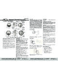
6 CAUTION: For use with air or compatible gases only. DWYER INSTRUMENTS, INC. Phone: 219/879-8000 BOX 373 MICHIGAN CITY, INDIANA 46360, Fax: 219/872-9057 e-mail: Series 1620 DIMENSIONS. SEALING DIAPHRAGM ADJUSTING NUT SEALING DIAPHRAGM ADJUSTING NUT. CALIBRATED RANGE SPRING CALIBRATED RANGE SPRING ADJUSTING SCREW. ADJUSTING NUT ADJUSTING NUT. ADJUSTING SCREW. SNAP switch SNAP switch . POWER DIAPHRAGM POWER DIAPHRAGM. 1/8 NPT FEMALE 1/8 NPT FEMALE. SHOWN WITH: ONE Single POLE DOUBLE THROW Switches SHOWN WITH: TWO Single POLE DOUBLE THROW Switches . OPTIONAL ENCLOSURES. Weatherproof Housing Note: Pressure and electrical connections must face down when mounted. 1-1/4. ( ) 2-21/64. ( ). 1/8 FEMALE NPT. 1-5/16 LOW Pressure . ( ) CONNECTION. 7. ( ) 1/8 FEMALE NPT. TYP HIGH Pressure . 8-13/16 CONNECTION. ( ) 1/2 FEMALE NPT. ELECTRICAL CONNECTION. 9-9/16 ( ) 1/2 ( ). CLEARANCE. 10-1/2 ( ) FOR COVER 3-5/64 ( ). 11-5/8 ( ) REMOVAL 4-57/64. ( ). Explosion-proof Housing Class I, Groups C Class II, Groups E, F Class III.
7 Warning: To reduce the risk of ignition of the hazardous atmosphere, conduit seals must be installed within 18 of this enclosure. Disconnect enclosure from supply circuit before opening. Keep assembly tight during operation. 7/16 ( ) MOUNTING. HOLE TYP 4 PLACES. 1/8 FEMALE NPT 3/4 FEMALE NPT. HIGH Pressure ELECTRICAL. CONNECTION CONNECTION. 11. BREATHER ( ). 6. 2-1/8 ( ). 12-1/8 ( ). ( ). 5-1/2 DRAIN. ( ) 13-5/8. ( ). 1/8 FEMALE NPT. LOW Pressure . 3-1/2 CONNECTION 3/4. 10-3/4 ( ). ( ) 3-1/2 ( ). 12 ( ) ( ). 1-3/4 ( ). CLEARANCE FOR 8-1/4. COVER REMOVAL ( ). Copyright 2015 Dwyer Instruments, Inc. Printed in 10/15 FR# 440199-00 Rev. 6. DWYER INSTRUMENTS, INC. Phone: 219/879-8000 BOX 373 MICHIGAN CITY, INDIANA 46360, Fax: 219/872-9057 e-mail.