Transcription of Bulletin E-56 Series 1900 Pressure Switch - Dwyer …
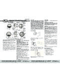
1 Bulletin E-56. Series 1900 Pressure Switch . Specifications - Installation and Operating Instructions 1/8 FEMALE NPT. HIGH PRESS. 60 TYP. CONNECTION. (2) 3/16 [ ]. 3 MOUNTING HOLES. [ ] 1-5/16 ON A 4-3/16 [ ] 3-1/2 [ ] 1/8 FEMALE NPT. [ ] TYP LOW Pressure . CONNECTION. 41/64 51/64. 7/8 [ ] [ ]. [ ] 1-19/32 CONDUIT 1-7/8. [ ] CONNECTION [ ]. 2-11/32 2-9/32. [ ] 1-3/4 [ ] [ ]. CLEARANCE 2-7/16 [ ]. FOR COVER. REMOVAL. Series 1910 Pressure Switch . All Series 1910 Switch with conduit The Dwyer -engineered force-motion amplifier increases the leverage of Pressure and electrical connections enclosure off. Shows electric Switch diaphragm movement and results in a Switch with excellent sensitivity and and set point adjustments are on one and set point adjustment screw. repeatability. side for easy installation. Advanced design and precision construction permit these switches to perform SPECIFICATIONS. many of the tasks of larger, costlier units.
2 Designed for air conditioning service, they Service: Air and non-combustible, compatible gases. also serve many fluidics, refrigeration, oven and dryer applications. For use with air Environment: Standard model intended for indoor use. and non-combustible gases. Series 1900 switches are available with set points of Wetted Materials: Consult factory. to 20 inches water column. Set point adjustment can be made easily - before or Temperature Limits: -30 to 180 F (-34 to C) (32 F for non dry air). after installation. Range screw is inside conduit enclosure to help prevent tampering. Pressure Limits: 45 ( kPa) continuous, 10 psig ( kPa) surge. For easy mounting and access, Pressure and electrical connections and set point Humidity Limit: 80% RH (non-condensing). adjustment are located on one side. This permits installation in corners or spaces too Altitude Limit: 6560 ft (2000 m) max. small for other switches. Switch Type: Single-pole double-throw (SPDT).
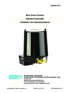
3 Repeatability: 3%. SPECIAL MODELS & ACCESSORIES Electrical Rating: 15 A @ 120-480 VAC (~), 60 Hz. Resistive 1/8 HP Special close coupled street elbow for right angle Pressure connections. Can be VAC(~), 1/4 HP @ 250 VAC(~), 60 Hz. Derate to 10 A for operation at high cycle installed on Switch anytime. Zinc plated aluminum. rates. Electrical Connections: 3 screw type, common, normally open and normally closed. Installation Category: III (transient over-voltage). Weatherproof Housing Process Connections: 1/8 female NPT. WEATHERPROOF ELECTRIC 1-1/8. 16 ga. steel enclosure with 4 [ ] SQ. CONNECTION HUB Mounting Orientation: Diaphragm in vertical position. Consult factory for other [ ]. gasketed cover (NEMA 4) 7/8 1/29 NPT FEMALE position orientations. [ ] (4) 5-16 [ ] DIA. Set Point Adjustment: Screw type inside conduit enclosure. for wet or oily conditions. MTG. HOLES NO. Withstands 200 hour salt Pollution Degree: 2.
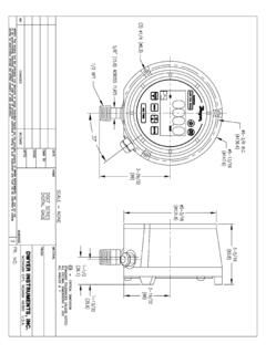
4 Spray test. Wt. 5 Ibs. ( NC Weight: 1lb. oz. (581 g). 2 [ ]. 3 [ ]. kg). Switch must be factory COM Agency Approvals: CE, UL, CSA, FM. installed. Change 1910 base POWER INPUT. number to 1911 and add -WP 3/4 TERMINALS. Explanation + of Symbols [ ] 3/4 [ ]. suffix. Example: 1911-1-WP. 3/32 Symbol Publication Description 1-1/4 [ ]. ~. 4-3/4 3 [ ]. [ ] 5-1/2 [ ]. HIGH PRESS. [ ] CONN. LOW PRESS. 3-1/8 [ ] GROUNDING IEC 60417 - 5032 Alternating current 1/8 CONN. 1/8 2-3/4 SCREW. 1/8 NPT HIGH Pressure CONN. [ ]. TAPPED FOR. 1-1/16 IEC 60417 - 5019 Protective conductor terminal Explosion-Proof Housing 4-1/4 6-1/2 [ ]. 1/2 ELECTRICAL. [ ]. [ ] CLEARANCE FOR. CONDUIT CONN. 1/2 NPT PROCESS. NEMA 7, 9 NEMA 3. (7 4X .281 [ ]. COVER REMOVAL CONNECTION. 5-3/4. lbs). Switch must be factory [ ] 4-1/4 Series 1910 Switches - Models Operating Ranges, Deadbands installed. Change model to [ ]. Operating Range, Approximate Dead Band 2X 4-1/4.
5 1911 and add -EXPL suffix. [ ] 1/16 4-5/16 [ ]. 5-3/4 1/8 NPT 6-1/8 [ ]. 2X LOW 5-13/32 [ ] Model in At Min. Set Point At Max. Set Point Example: 1911-1-EXPL. [ ] Pressure . [ ]. CONN. 1910-00 to Aluminum base and cover 3X 1-1/16. 1/8 FEMALE NPT. [ ] 1910-0 to rated Class I, Groups C & D, LOW Pressure CONNECTION. 3 [ ] 1910-1 to Div. 1. Class II, Groups E, F, 1/8 FEMALE NPT 6-5/8 [ ]. HIGH Pressure CONNECTION 1910-5 to & G, Div. 1. 1910-10 to 1910-20 to Dwyer INSTRUMENTS, INC. Phone: 219/879-8000 BOX 373 MICHIGAN CITY, INDIANA 46360, Fax: 219/872-9057 e-mail: INSTALLATION OPERATION. 1. Select a location that is free from excessive vibration, corrosive atmosphere and Pressure acting on the power diaphragm rotates the amplifying lever, which in turn where the ambient temperature is within the limits for these switches. extends the range spring and rotates the snap Switch input lever. When the set point is reached, the snap switcch is actuated and the electrical contacts make or break.
6 2. Mount standard switches with the diaphragm in a vertical plane and with Switch lettering and nameplate in an upright position. Some switches are position sensitive ADJUSTMENT. and may not reset properly unless they are mounted with the diaphragm vertical. To change the set point, proceed as follows: (Special units can be furnished for other than vertical mounting arrangements if A. Remove the snap-on cover from the conduit enclosure by loosening its retaining required.) screw and pulling firmly at its bottom end. Turn the slotted adjustment screw at the top of range spring housing clockwise to raise the set point Pressure and counter- 3. Connect Switch to source of Pressure , vacuum or differential Pressure . Metal tubing clockwise to lower the set point. with 1/4 is recommended, but any tubing which will not restrict the air flow can be used. Connect to the two 1/8 female NPT Pressure ports as noted below: B. The recommended procedure for calibrating or checking calibration is to use a T assembly with three rubber tubing leads, all as short as Differential pressures - connect pipes or tubes from source of greater Pressure to possible and the entire assembly offering minimum flow restriction.
7 Run one lead to high Pressure port marked HI-PR and from source of lower Pressure to low Pressure the Pressure Switch , another to the manometer of known accuracy and appropriate port marked LO-PR. range, and apply Pressure through the third tube. Make final approach to the set point Pressure only (above atmospheric) - connect tube from source of Pressure to high very slowly. Note that manometer and Pressure Switch will have different response Pressure port. The low Pressure port is left open to atmosphere. times due to different internal volumes, lengths of tubing, fluid drainage etc. Be certain Vacuum only (below atmospheric Pressure ) - connect tube from source of vacuum to the Switch is checked in the position it will assume in use, with diaphragm in a low Pressure port. The high Pressure port is left open to atmosphere. vertical plane and Switch lettering and nameplate in an upright position. C. For highly critical applications it is a good idea to check the set point adjustment CAUTION Power must be off while wiring connections are being made.
8 And reset it as necessary once or twice in the first few months of operation. This will compensate for any change in initial tension which may occur in the spring and 4. Electrical connections to the standard single pole, double throw snap Switch are diaphragm. For most applications this change will not be significant and no resetting provided by means of screw terminals marked common , norm open , and norm will be required. closed . The normally open contacts close and the normally closed contacts open when Pressure increases beyond the set point. MAINTENANCE. Moving parts of these switches are sealed in and are permanently tamper proof. The CAUTION Do not exceed the specified voltage rating. Permanent damage single adjustment is that of the set point. Care should be taken to keep the Switch not covered by warranty may result. reasonably dry and free from dust or dirt. No lubrication or unusual precautions are required for normal use.
9 5. Switch loads should not exceed the maximum specified current rating of 15 amps resistive. Switch capabilities decrease with high load inductance or rapid cycle rates. Whenever an application involves either of these factors, the user may find it desirable to limit the switched current to 10 amps or less in the interest of prolonging Switch life. Dwyer INSTRUMENTS, INC. Phone: 219/879-8000 BOX 373 MICHIGAN CITY, INDIANA 46360, Fax: 219/872-9057 e-mail: Bulletin E-56. Presostatos Serie 1900.. Instrucciones de Montaje y Operaci n 1/8 FEMALE NPT. HIGH PRESS. 60 TYP. CONNECTION. (2) 3/16 [ ]. 3 MOUNTING HOLES. [ ] 1-5/16 ON A 4-3/16 [ ] 3-1/2 [ ] 1/8 FEMALE NPT. [ ] TYP LOW Pressure . CONNECTION. 41/64 51/64. 7/8 [ ] [ ]. [ ] 1-19/32 CONDUIT 1-7/8. [ ] CONNECTION [ ]. 2-11/32 2-9/32. [ ] 1-3/4 [ ] [ ]. CLEARANCE 2-7/16 [ ]. FOR COVER. REMOVAL. Series 1910 Pressure Switch . All Series 1910 Switch with conduit The Dwyer -engineered force-motion amplifier increases the leverage of Pressure and electrical connections enclosure off.
10 Shows electric Switch diaphragm movement and results in a Switch with excellent sensitivity and and set point adjustments are on one and set point adjustment screw. repeatability. side for easy installation. El diseno avanzado y la constucci n prcisa permitne que estospresostatos SPECIFICATIONS. reemplacen a otros de mayor precio y tama o. Sirven para uso en acondicionamiento Servicio: Aire y no combusibles, gases compatibles. de aire, hornos, secaderos y aplicaciones en flu dica y refrigeraci n. Aptos para uso Ambiente: Para uso en interiores. en aire y gases no combustibles. Ranges disponibles desde a 20 de Materiales mojados: Consulte con la f brica. El ajuste puede ser antes o despu s de instalado. El tornillo de ajuste est oculto L mites de temperature: -30 to 180 F (-34 to C). dentro de la cubierta de conexiones para evitar manipuleo indebido. El ajuste, las L mites de presi n: 45 ( kPa) continuo, 10 psig ( kPa) marejada.