Transcription of Capacitors for A.C. motor applications
1 Capacitors for motorapplications ContentsPageGeneral information2 to 7 Capacitor selection guide8 to 10 Plastic case series11 to 37 Metalcaseseries39to52 Boxseries53to56 Mechanical drawings57 to 64 KEMET reserves the right, at any time, to make any changes to the components, parts and accessoriesboth for technical and commercial purposes without necessarily reprinting this catalogue cannot be considered as a Technical Specification. For further information please refer to theInternet site http:\\ INFORMATION2 TECHNICAL TERMS EXPLANATIONR ated capacitance of the capacitor C( F):the capacitance value for which the capacitor has beendesigned, measured at 20 C at frequency of voltage Un(V):the effective value of voltage for which the capacitor has been designedRated frequency Fn(Hz): the highest value of frequency for which the capacitor has been designedRated current In(A): the effective value of alternating current to the rated voltage and operating temperature( C):the minimum permissible temperature on the external surface of thecapacitor can during its operating temperature( C).
2 The maximum permissible temperature over the external surface ofthe capacitor can during its for continuous and intermittent working:a capacitor designed to work at a certain voltageduring continuous working and at a different voltage (normally higher) during intermittent classes:the total length of minimum life for which the capacitor has been designed underconditions of voltage, temperature, frequency, rated cycle:Class hoursClass hoursClass hoursClass hoursThese working classes expect a failure rate not higher than 3% during the life of the category:is specified by three digits (IEC 60068-1). The first number represents the lower limit, thesecond one represents the higher limit, the third one represents the number of days necessary to thehumidity test (example 25/100/21).
3 Dissipation of a capacitor(W):the dissipated active power of the capacitor .Dissipation factor(tg ):the relation between the resistance equivalent series and the capacitive reactanceto an alternating sinusoidal voltage and to a specific Resistance:the relation, measured by M , between a continuous voltage applicated to thecapacitor and the creepage current after one charge current of creepage(A):the current passing a conductor which connects the metallic can to theground when the capacitor is powered by an alternating current system with the grounded to transistor:pulse rise time (dv/dt). It characterizes the capacitance of a capacitor to withstandcurrent peaks due to fast changes of voltage. The peak current is quantifiable by the following formula:IPEAK(A)= C ( F) * dV/dt (V/ S)Working and Safety conditionsApplication:the Capacitors described in the current catalogue are specifically designed for the start and therun of single-phase electric motors.
4 Usually the capacitor is connected in series to an inductive winding intoan auxiliary circuit for a single-phase motor or in parallel phase/phase into three-phase motors whenpowered by a single-phase class:the degreee of safety is marked on the capacitor according to the following symbols:(P2)the capacitor has been designed to fail only in case of circuit cut-off and it is protected against fireand electrocution risk.(P1)the capacitor can fail either by a circuit cut-off or by a short-circuit and it is protected against fireand electrocution risk.(P0)in case of failure, the capacitor does not have any particular device: KEMET produces Capacitors according to high level of process and quality the usual working, due to external stresses or at the end of the life, the capacitor canstop working.
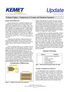
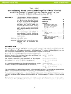
5 In order to guarantee a better internal safety, KEMEThas developed series (metalliccan)including an internal double safety device. The internal pressure due to gas in case of overheating,causes the expansion of the groove disconnecting the capacitor from the electric network (see picture pg. 7).GENERAL INFORMATION3 Rated Voltage:is the highest continuous voltage applicable to the capacitor at rated temperature. Highercontinuous voltage may cause the perforation of the dielectric or a short-circuit. The material used asdielectric owns a typical property, well-known as self-healing : in case of discharge, the temperature createsa localized demetallization which insulates the discharge process. The rated voltage belongs to thealternating sinusoidal :the power dissipated by the capacitor is quantifiable by the following formula:P max(W) = 2* *f * C * tg *V2 RMSThe current passing the capacitor causes a heating of the component.
6 If the heat is excessive, theperformances of the component can get worse to the short-circuit, the out-of-working and the fire the current applied is generated by a periodical sine wave, the whole cartridge could heat. It will benecessary to check the temperature does not exceed the maximum permissible the current is generated by non-periodical waves (pulse and harmonic currents) a heating localized overthe terminals could occur, in addition to an heating of the component. In this case, it will be necessary tocheck the sealing of the capacitor at current peak (dv/dt).Ionization processes:the dielectric strength is the key characteristic to choose a dielectric the voltage, there is a value where the dielectric loses his insulating properties and the passageof a strong conduction current occurs: this is the discharge process.
7 Even if the discharge is generally athermal process, it is important to know the voltage applied: normally, the dielectric strength has minimumvalues with alternating voltages (thermal discharge) and maximum values with pulse voltages (electronic orintrinsic discharge).Together with these two processes, there is to consider the process of partial discharges due to the ageingof the material and to external stresses, some vacuoles are born, points of partial discharges. Thesedischarges cause a progressive expansion of empty spaces with and a consequent erosion process taking tothe definitive :particular conditions of temperature and relative humidity may cause a deterioration of the electriccharacteristics of the the following parameters in order to carry out a correct storage:Temperature: from 5 to 50 CHumidity Average yearly value: 60% All other days: 70% For 30 days spread over the year (statistical data) : 80%GENERAL INFORMATION4 Expected LifeAny material or element has a longer or shorter life according to the working conditions to which it issubmitted and to its intrinsic property.
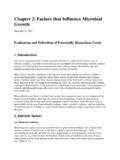
8 The capacitor is submitted to several types of stresses: over voltages,overheating, pollution, humidity, radiations, vibrations .. The ageing is an irreversible change of theproperties as a result of the application of an external stress. The expected life is time necessary to thecapacitor to reach the expected limit main stresses have electric and thermal origin. It is possible to assume a model of life for each series ofproduct and type of stress so as to expect the life of the component in function of temperature and (hours) = F (V, T).In the catalogue, here below, the curves of expected life in function of the voltage applied to the component,referred to rated temperature. These curves refer to life tests fixed by EN60252 standard where it is alloweda maximum variation of capacitance of 3%.
9 Please get in touch with KEMETfor further details. MaterialsThe materials used for KEMET Capacitors are the result of long experience and constant attention to fieldimprovements. KEMET, certified according to ISO9001 standard, selects its suppliers and carries outsystematical checks to the step of materials acceptance. All materials to our present knowledge are non-toxic and free from: Cadmium, Mercury, Chrome and compound, PCB (PolyChlorineTriphenyl), Bromide andChlorine Dioxins, CFC e HCFC, Capacitors can be disposed of in compliance with the laws in force (DL22/97) according to the SeriesCER 150106 Special waste not SeriesCER 150106 Special waste not SeriesCER 150106 Special waste not dangerous GENERAL INFORMATION5 C/C [%]-3-2-1012-75-50-250255075100T[ C] C/C [ %]-1,5-1-0,501101001000f[kHz]tg x10-41101001101001000f[kHz]M x F[s]1E+021E+031E+041E+051E+060 255075100125 Ctg x10-501020304050-75-50-250255075100T[ C]GENERAL INFORMATION6 PRODUCT CODIFICATIONC274AA34250AA0 JInternal variantThe digits 9,10,11 specify the capacitance, while the digit8 specifies the number of 0 s to be added to obtain therated capacitance in percentage on capacitanceJ 5%K 10% XSpecialtolerance Termination 1 Fast-on x (hole)2 Single Fast-on x 3 Double Fast-on x x (slot) 5 Fast-on x (hole) unipolar cable, section mm2 FBipolar cable.
10 40mm unsheating 8mm stripped tinned JBipolar cable: End terminal HBipolar cable: Straight fast-on GBipolar cable: Straight female fast on LBipolar cable: Flag female fast-on KBipolar cable: Flag female fast-on IBipolar cable: Ring M4 terminal RStiff unipolar cable, section mm2 ZSpecial terminationCan and fixing device APlastic can without fixing bolt BPlastic can with M8 x 10 plastic fixing bolt CPlastic can with M8 x 10 metal fixing bolt DEPlastic can with quick fit connectionAluminium can without fixing bolt FAluminium can with M8 x 10 fixing bolt GAluminium can with M12 x metal fixing boltMarking - (UL) (UL) NC27 (UL) ZSpecial markingProduct seriesPlastic can:C87 SeriesGENERAL INFORMATION7 TRACEABILITY OF THE PRODUCTKEMET assures the whole traceability of the product by marking each component with day, month, yearandproduction line coded according to an international standard (IEC62).