Transcription of CCNA 2: Student Lab Manual v5
1 ccna 2: Student Lab Manual Student 1 name: _____. Student 1 number: _____. Student 2 name: _____. Student 2 number: _____. Student class ID: _____. Date when this workbook was submitted: _____. All contents are Copyright 1992 2007 Cisco Systems, Inc. All rights reserved. This document is Cisco Public Information. Page 1 of 168. ccna 2 Exploration - Internetworks Routing Protocols and Concepts Lab : Cabling a Network and Basic Router 3. Lab : Basic Router Configuration .. 21. Lab : Challenge Router 29. Lab : Basic Static Route Configuration .. 32. Activity : Subnetting Scenario 1 .. 51. Lab : Basic RIP 55. Scenario A: Running RIPv1 on Classful 56. Scenario B: Running RIPv1 with Subnets and Between Classful 61. Lab : RIP 66. Activity : Basic VLSM Calculation and Addressing 76. Lab : RIPv2 Basic Configuration Lab .. 81. Lab : RIPv2 Troubleshooting Lab.
2 91. Lab : Investigating the Routing Table Lookup 103. Scenario A: Level 1 and Level 2 Routes .. 104. Scenario B: Classful and Classless Routing 108. Lab : Basic EIGRP Configuration Lab .. 112. Lab : EIGRP Troubleshooting Lab .. 126. Lab : Basic OSPF Configuration Lab .. 137. Scenario A: Basic OSPF 138. Scenario B: Configure OSPF on a Multiaccess Network .. 151. Lab : OSPF Troubleshooting Lab .. 158. ccna 2 Exploration - Internetworks 3/168. Routing Protocols and Concepts Lab : Cabling a Network and Basic Router Configuration Topology Diagram Addressing Table Devi Subnet Default Interface IP Address ce Mask Gateway Fa0/0 N/A. R1 0. S0/0/0 N/A. 0. Fa0/0 N/A. R2 0. S0/0/0 N/A. 0. PC1 N/A 0. PC2 N/A 0. Learning Objectives Upon completion of this lab, you will be able to: Cable devices and establish console connections. Erase and reload the routers.
3 Perform basic IOS command line interface operations. Perform basic router configuration. Verify and test configurations using show commands, ping and traceroute. Create a startup configuration file. Reload a startup configuration file. Install a terminal emulation program. Scenario In this lab activity, you will review previously learned skills including cabling devices, establishing a console connection, and basic IOS command line interface operation and configuration commands. You will also learn to save configuration files and capture your configurations to a text file. The skills presented in this lab are essential to completing the rest of the labs in this course. However, you may substitute the shorter version, Lab : Basic Router Configuration, if your instructor determines that you are proficient in the essential skills reviewed in this lab.
4 ccna 2 Exploration - Internetworks 4/168. Routing Protocols and Concepts Task 1: Cable the Ethernet Links of the Network. Cable the Ethernet links for a network that is similar to the one in the Topology Diagram. The output used in this lab is from Cisco 1841 routers. But you can use any current router in your lab as long as it has the required interfaces as shown in the topology. A simple way to identify the available interfaces on a router is by entering the show ip interface brief command. Which of the devices in the Topology Diagram require an Ethernet cable between them? _____. Step 1: Connect the R1 Router to the S1 Switch. Use a straight-through Ethernet cable to connect the FastEthernet 0/0 interface of the R1 router to the FastEthernet 0/1 interface on the R1 switch. What color is the link status light next to the FastEthernet 0/0 interface on R1?
5 _____. What color is the link status light next to the FastEthernet 0/1 interface on S1? _____. Step 2: Connect PC1 to the S1 Switch. Use a straight-through Ethernet cable to connect the network interface card (NIC) of PC1 to the FastEthernet 0/2 Interface of the S1 switch. What color is the link status light next to the NIC interface on PC1? _____. What color is the link status light next to the FastEthernet 0/2 interface on S1? _____. If the link status lights are not green, wait a few moments for the link between the two devices to become established. If the lights do not turn green after a few moments, check that you are using a straight-through Ethernet cable and that the power is on for the S1 switch and PC1. Step 3: Connect PC2 to the R2 Router. Use a crossover Ethernet cable to connect the FastEthernet 0/0 interface of the R2 router to the NIC of PC2.
6 Because there is no switch between PC2 and the R2 router, a crossover cable is required for a direct link between the PC and the router. What color is the link status light next to the NIC interface on PC2? _____. What color is the link status light next to the FastEthernet 0/0 interface on R2? _____. Task 2: Cable the Serial Link between the R1 and R2 Routers. In a real-world WAN connection, the customer premises equipment (CPE), which is often a router, is the data terminal equipment (DTE). This equipment is connected to the service provider through a data circuit-terminating equipment (DCE) device, which is commonly a modem or channel service unit (CSU)/ data service unit (DSU). This device is used to convert the data from the DTE into a form acceptable to the WAN service provider. Unlike the cables in the academy lab setup, the serial cables in the real world are not connected back to back.
7 In a real-world situation, one router might be in New York, while another router might be in Sydney, Australia. An administrator located in Sydney would have to connect to the router in New York through the WAN cloud in order to troubleshoot the New York router. In the academy labs, devices that make up the WAN cloud are simulated by the connection between the back-to-back DTE-DCE cables. The connection from one router serial interface to another router serial interface simulates the whole circuit cloud. Step 1: Create a null serial cable to connect the R1 router to the R2 router. In the academy labs, the WAN connection between routers uses one DCE cable and one DTE. cable. The DCE-DTE connection between routers is referred to as a null serial cable. The labs will use one DCE cable and one DTE cable to simulate the WAN connection.
8 The DCE. ccna 2 Exploration - Internetworks 5/168. Routing Protocols and Concepts connector is usually a female (34-pin) connector. The DTE cable has a male connector. The cables are also labeled as DCE or DTE on the router end of the cable. The DTE and DCE cables must be joined together. Holding one of the ends in each hand, examine the pins and sockets as well as the threaded connectors. Note that there is only one proper way for the cables to fit together. Align the pins on the male cable with the sockets on the female cable and gently couple them. Very little effort should be required to accomplish this. When they are joined, turn the thumbscrews clockwise and secure the connectors. Step 2: Connect the DCE end of the null serial cable to the Serial 0/0/0 interface of the R1. router, and the DTE end of the null serial cable to the Serial 0/0/0 interface of the R2 router.
9 Review the information provided below before making these connections. Before making the connection to one of the routers, examine the connector on the router and the cable. Note that the connectors are tapered to help prevent improper connection. Holding the connector in one hand, orient the cable and router connecters so that the tapers match. Now push the cable connector partially into the router connector. It probably will not go in all the way because the threaded connectors need to be tightened in order for the cable to be inserted completely. While holding the cable in one hand and gently pushing the cable toward the router, turn one of the thumb screws clockwise, 3 or 4 rounds, to start the screws. Now turn the other thumbscrew clockwise, 3 or 4 rounds, to get it started. At this point the cable should be attached sufficiently to free both hands to advance each thumbscrew at the same rate until the cable is fully inserted.
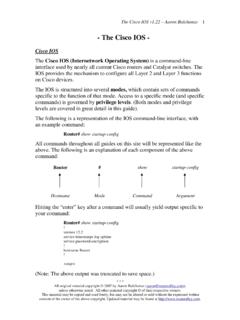
10 Do not over-tighten these connectors. Task 3: Establish a Console connection to the R1 Router. The console port is a management port used to provide out-of-band access to a router. It is used to set up the initial configuration of a router and to monitor it. A rollover cable and an RJ-45 to DB-9 adapter are used to connect a PC to the console port. As you know from your previous studies, terminal emulation software is used to configure the router over the console connection. The Cisco Networking Academy Program recommends using Tera Term. However, you can also use HyperTerminal, which is part of the Windows operating system. At the end of this lab, the following three appendices are available for your reference concerning these two terminal emulation programs: Appendix 1: Installing and Configuring Tera Term for use on Windows XP.