Transcription of Challenges of designing high-frequency, high-input …
1 28 Analog Applications JournalTexas instruments IncorporatedHigh-Performance Analog Products 2Q 2011 Power ManagementChallenges of designing high-frequency, high-input -voltage DC/DC convertersDC/DC converters are being designed with ever faster switching frequencies in an effort to decrease the size of the output capacitor and inductor to save board space. Because of this, more DC/DC converters that operate at higher input voltages are now on the market that provide protection from line transients, making lower voltages difficult to achieve at faster frequen-cies due to the lower duty cycle. Many manufacturers of power integrated circuits (ICs) are aggressively market-ing high-frequency DC/DC converters that they claim reduce board space. A DC/DC converter operating at 1 or 2 MHz seems like a great idea, but the switching frequency impacts the power-supply sys -tem in more ways than just its size and efficiency.
2 This arti -cle presents several design examples that demonstrate the benefits and Challenges of switching at higher an applicationTo show the trade-offs of using high switching frequencies, three independent power supplies were designed and built with respective operating frequencies of 100, 300, and 750 kHz. For all three designs, the input voltage was 48 V, the output voltage was 5 V, and the output current was 1 A. These requirements are typical for powering a 5-V logic USB or an intermediate, general 5-V bus to be used by other DC/DC converters, such as low-dropout regulators. To establish design limitations, the allowable ripple voltage chosen was 50 mV, which was about 1% of the output voltage; and a peak-to-peak inductor current of A was chosen. The texas instruments TPS54160, which is a , 60-V, step-down DC/DC converter with an integrated MOSFET, was used as the regulator in each design.
3 The TPS54160, featuring external compensation and a fast programmable frequency, is intended for indus-trial applications with high input the inductor and capacitorThe inductor and capacitor for each scenario were chosen according to the following four simplified formulas:By Richard Nowakowski, Power Management Product Marketing,and Brian King, Applications Engineer, Member Group Technical StaffFor the inductor, (1a)This can be rearranged as ()OUTD iodes1 DLVV,If + D (1b)where D (the duty cycle) = 5 V/48 V = , and DI = A peak to the capacitor, (2a)This can be rearranged as s2IC,8fV D D (2b)where DI = A peak to peak, and DV = 50 Equation 2b it is assumed that the capacitor chosen has negligible equivalent series resistance (ESR), which is true for ceramic capacitors.
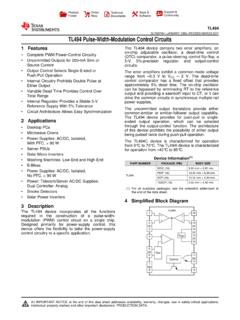
4 Ceramic capacitors were cho-sen for all three designs because of their low resistance and small size. The multiplier of 2 in the numerator of Equation 2b accounts for the capacitance drop associated with DC bias, since this effect is not accounted for in the datasheets of most ceramic circuit in Figure 1 was used to evaluate the perform-ance of each design on the bench. The components in the schematic that do not have values are the components that were modified in each design. The output filter consists of kWR3R25-V FU1 TPS54160 DGQBOOTVINENSS/TRRT/CLK12345109876 PHGNDCOMPVSNSPWRGDF igure 1. TPS54160 reference schematicTexas instruments Incorporated29 Analog Applications Journal2Q 2011 High-Performance Analog ProductsPower ManagementL1 and C2. The values of these components for all three designs are listed in Table 1 and were chosen based on the results from Equations 1a through 2b.
5 Note that the DC resistance of each inductor decreased as the frequency increased. This is due to less copper length being needed for fewer turns. The error amplifier s compensation com-ponents were designed independently for each switching frequency. The calculations for selecting the compensation values are beyond the scope of this ON timeDC/DC converter ICs are characterized by a limit on the minimum controllable ON time, which is the narrowest achievable pulse width of the pulse-width-modulation (PWM) circuit. In a buck converter, the percentage of time that the power MOSFET is on during a switching cycle is called the duty cycle and is equal to the ratio of the output voltage to the input voltage. For the TPS54160 converter, the duty cycle is (5 V/48 V), and the minimum ON time as shown in the datasheet is 130 ns.
6 The limit for the controllable pulse width results in a minimum achievable duty cycle, which can be easily calculated by multiplying the minimum ON time by the switching frequency. Once the minimum duty cycle is known, the lowest achievable output voltage can be calculated by multiplying VIN by the minimum duty cycle. The lowest output voltage is also limited by the reference voltage of the converter, which is V for the this example, a 5-V output can be generated with a 750-kHz switching frequency (see Table 2). However, if the frequency is 1 MHz, the lowest possible output voltage is limited to about 6 V; otherwise the DC/DC converter will skip pulses. The alternative is to lower the input voltage or the frequency. It is a good idea to check the DC/DC con-verter datasheet for a guaranteed minimum controllable ON time before selecting a switching skippingPulse skipping occurs when the DC/DC converter cannot extinguish the gate-drive pulses fast enough to maintain the desired duty cycle.
7 The power supply will try to regu-late the output voltage, but the ripple voltage will increase due to the pulses being further apart. Due to the pulse skipping, the output ripple will exhibit subharmonic com-ponents, which may present noise issues. It is also possible that the current-limiting circuit will no longer work prop-erly, since the IC may not respond to a large current spike. In some cases, the control loop may be unstable if the con-troller is not performing and power dissipationThe efficiency of a DC/DC converter is one of the most important attributes to consider when designing a power supply. Poor efficiency translates into higher power dissi-pation, which has to be managed with separate heat sinks or additional copper on the printed circuit board (PCB). Power dissipation also places a higher demand on the power supply upstream.
8 Power dissipation has several components, shown in Table loss components of interest from the three examples come from the FET driving loss, the FET switching loss, and the inductor loss. The FET resistance and IC loss are consistent since the same IC is used in all three designs. Since ceramic capacitors with low ESR were chosen in Table 2. Minimum output voltage with 130-ns minimum ON timeSWITCHINGFREQUENCYMINIMUMDUTY CYCLEMINIMUM VOUTat 48 VIN(V)100 kHz0 .0130 .8 (VREF)300 kHz0 .0391 .87750 kHz0 .0984 .71 MHz0 .136 Table 1. Capacitor and inductor selections for three example power-supply designsSWITCHINGFREQUENCY(kHz)C2( F)/SIZEL1( H)L1DC RESISTANCE(max) (mW)10047/1206100240 .930010/0805331807504 .7/060315135 Table 3. Power-dissipation componentsLOSS COMPONENTFACTORSFET driving lossFunction of gate charge, drive voltage, frequencyFET switching lossFunction of VIN, IOUT, FET rise/fall time, frequencyFET resistanceI2 RDS(on)Diode lossVf IOUT (1 D)Inductor lossI2 DC resistance + AC core lossCapacitor lossIRMS2 ESRIC loss (IQ)Datasheet specification for IQ for when the IC is operatingTexas instruments Incorporated30 Analog Applications JournalHigh-Performance Analog Products 2Q 2011 Power Managementeach example, the capacitor loss is negligible.
9 To show the effects of high-frequency switching, the efficiency of each example was measured and is illustrated in Figure 2. The figure clearly shows that the efficiency decreases as switch-ing frequency is increased. To improve efficiency at any frequency, look for a DC/DC converter with a low drain-to-source ON resistance, a gate charge, or a quiescent-current specification at full load; or search for capacitors and induc-tors with lower equivalent sizeTable 4 shows the total board area required for the three designs along with the pad areas of the capacitor and inductor. The recommended pad area of a capacitor or inductor is slightly larger than the individual component itself and is accounted for in each of the three design examples. The total area was derived by adding the area occupied by each component, which includes the pad sizes for the IC, the filter, and all other small resistors and capacitors, and multiplying the result by a factor of 2 to account for component spacing.
10 The total area savings of almost 250 mm2 between the 100-kHz and 750-kHz designs is significant, providing a 50% reduction in filter size and a 55% reduction in board space. However, the law of diminishing returns applies, since the capacitance and inductance values cannot be reduced to nothing! In other words, pushing the frequency higher will not continually reduce the overall size, since there is a limit to the avail-ability of appropriately sized, mass-produced inductors and capacitors. Note that the 33- H and 15- H inductors occupy the same area. This is possible because the 33- H inductor is mm tall, whereas the 15- H inductor is only mm tall. These two inductors were chosen to illustrate the point that the inductance is proportional to the responseThe transient response is a good indicator of the perform-ance level of a power supply.