Transcription of Complete Dovetail Jig Instructions
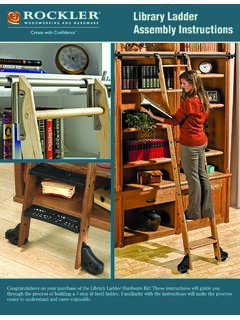
1 IntroductionYour new Dovetail jig will cut Full ThroughDovetails and three varieties of Half BlindDovetails (flush half blind, offset half blindand rabbeted half blind). (Figure 1) It willalso cut Box ( also known as finger )Joints. It will accommodate stock from1/2" to 11 8" thick and up to 11" wide. The following Instructions begin by detail-ing how to set up the jig for basic 1/2" and3/4" material to mill flush half-blind dovetailsand full through dovetails (Fig. 1). Once youhave mastered this technique, you can add other jointsto your repertoire such as offset dovetails, rabbeteddovetails and box joints. (See page 8 for details.)Square and flat material is key to the success of perfectly aligned joints.
2 For any of the joints being cut, always cut additional pieces the exact size of those being used in your project to experiment with the settings for joint accuracy1 Clamp Handle (2)2 Cam (4)3 Clamp Axle (2)4 Stop Bar (1)5 Clamp Bar (2)6 Pin Template7 Clamp Springs (not shown)8 Fence Lock Knobs (2)91/2" Half-Blind/Tails Template (1)10 Jig Body (1)11 L Shaped Adjustable Stops (2)12 Cam Lock Knob (4)13 Cam Lock Housing (4)14 Template Adjustment Bar (2)151/2"-14 Dovetail Bit161/2"-8 Dovetail Bit175/16" Straight Bit181/2"-8mm Collet Reducer19 Template Guide Bushing SetPARTS LIST - COMPLETEDOVETAILJIGC omplete Dovetail Jig Instructions1345681213991411101917161815 2 Through DovetailsHalf Blind DovetailsFigure 11(22818)RTD10000332 AASecure the JigTwo holes in the bottom of the jig allow permanent attachment to a work-bench or similar stable base.
3 Where work space is limited, the same holesallow mounting to a shop-built movable base (Fig. 2) that can be secured inthe jaws of a vise. The jig can then be stored elsewhere when not in base is just two pieces of sheet stock (plywood, MDF, melamine, etc.)screwed together at 90 . An optional glued dado strengthens the joint andprovides extra Up the RouterIncluded with your jig are a 1/2"-14 Dovetail bit for half blind dovetails,1/2"- 8 Dovetail bit and 5/16" straight bit for full through Dovetail joints. Alsoincluded is a 1/2"-8mm reducer for your 1/2" router collet. The 8mm shanksize will significantly reduce the amount of chatter and offer a cleaner included is a 7/16" guide bushing assembly.
4 The bushing is universal: it fits most popular brands of routers and after-market bases. (In the remotechance that you have difficulty attaining a perfect fit, consult your router smanufacturer; they usually offer a guide bushing as an option.)HALF-BLIND INSTRUCTIONSD rawer Layout It is recommended that you keep track of the parts of each drawer by numbering and labeling them, then milling them in the same order everytime you build a drawer or box. This repetition will virtually eliminate mistakes, with to the drawing above to see how this is done. The parts of the drawerare laid out in their proper orientation, then each piece is labeled on theinside face (FRONT, BACK, LEFT SIDE, RIGHT SIDE).
5 You can write directly on the part with a soft pencil, or use masking the faces next: each face should have a notation that says which wayis up. Finally, mark the corners with designated number, 1 through 4. Forexample, the left side of the drawer in the illustration meets the front at corner #1, so each part is so labeled. If you can develop a habit of markingthe drawers in exactly the same fashion every time, errors will be few andfar the bushing in the router base and secure it with the included threaded ring. Tighten the ring securely, then slide the base toward themotor housing and install the bit. For half blind Dovetail joints you will be using the 1/2" x 14 Dovetail of cut will be 9/16" from the base of your router.
6 Included on the halfblind template is a gauge for setting this height (Fig. 3). Adjusting for jointtightness will be covered later in these shop-built baseallows for quick setupin the workbench vise,and easy 213312 24 4 FRONTBACKLEFTRIGHT14 Left side up2 Figure 3 Locate the StopsThe jig is equipped with two stops (Fig. 4) that locate the drawer parts and allowrepetitive milling; once they are set you can build as many drawers as you first step is to to ensure that the dovetails are evenly spaced on your workpiece (that is, there is the same amount of pin or tail top and bottom). With thehalf blind (straight fingers) template installed, slide a piece of scrap the samewidth as your drawer stock into the jig.
7 Center the board (left and right) on thetemplate fingers, as shown in Figure 5. The idea is to have the same amount offinger or gap showing at each side of the board. Make sure the board lies at 90 to the front of the jig, then loosen the three screws in the adjustable stop (the leftone, Part 11, see (Fig. 6), and slide it snug against the board. Tighten the threescrews. Repeat this process for the right side of the the Drawer PartsDuring initial set-up adjustment, always use test pieces the same thickness andwidth as your drawer sides that you will be milling. Only install the actual drawersides after you ve produced a satisfactory joint in the test pieces. Figures 6, 7and 8 illustrate the process involved in installing the two boards for each that the two left-hand joints (that is, the joints that attach the left drawerside to the drawer front and back) are cut at the left side of the jig.)
8 Subsequently,the two right-hand joints will be milled at the right-hand side of the Tip:Always position drawer parts so inside is facing by installing the drawer s left side in the front of the jig (vertically), andsecuring it with the cam lock. You may have to adjust the cam lock for a good fit;don t over-tighten it. The top edge of the work piece should protrude above thejig body (Fig. 6), but perfect alignment isn t necessary at this Tip:For even clamping, always use scrap wood the same thickness as your stock as support on the opposite end of the the drawer front into the top of the jig (horizontally). The inside face of thispart should be facing up. Butt the drawer front tightly against the drawer side (Fig.)
9 7), check that it is tightagainst the stop (Part 11), and secure it in place with the cam you can slide the drawer side up so that its top edge is flush with the topface of the drawer front as shown (Fig. 8). Secure the drawer side in place, tightagainst the stop (Part 11), by engaging the front cam 4 Figure 6 SupportscrapFigure 7 Figure 8 Equal distanceFigure 53 Set the TemplateFor 1/2" material, set the back edge of the half blind template to the A setting (Fig. 9) on the adjustment arm. For 3/4" thick material use the B setting (Fig. 9). All the template settings for 1/2" and 3/4" material are designed as startingpoints to rout your joints. Depending on material thickness, tolerances in theguide bushings and router bits, the template may need minor adjusting to giveyou the desired final fit.
10 Set the Stop BarThe last adjustment to make before milling begins is to set the Stop Bar (Part 4).Two knobs (Parts 8) lock the Stop Bar in reason you set the Stop Bar is that the router base butts up against it at the end of every cut. This limits the length of the grooves between the pins intowhich the tails fit. Note the different lengths of the grooves (Figures 10 and 11). Both of these settings are for Porter-Cable (53 4") base dimensions. If you are using a router with a base that s not 53 4" diameter, you need to use the following formula for setting the fence. Setting the fence location soundscomplicated, but it s really quite simple. You ll need a piece of paper and a pencilto work out the location, since you ll need to add a couple of numbers by writing down a measurement that is twice the thickness of the drawerside stock (for example, with 3/4" thick sides, this would be 11 2").