Transcription of Contents
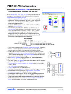
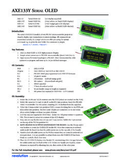
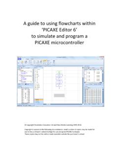
1 axe118 picaxe -20M PROJECT BOARD KITrevolutionRevolution Education Ltd. Email: Web: 30/01 : PCBAXE118 Project board PCB R110k resistor (brown black orange gold) RPU/RPD 10k resistor (brown black orange gold) R222k resistor (red red orange gold) RA17x10k 8pin resistor array (common is by dot) C1100nF polyester capacitor CT1stereo download socket BCBattery Clip IC120 pin IC socket IC218 pin IC socket IC2 ULN2803A darlington driverDescription:The picaxe -20M project board provides a rapid development system for the picaxe -20M microcontroller system. Itprovides the basic download circuit, connection points for inputs / outputs, and an optional darlington driverbuffered output circuit ( each output is buffered by the ULN2803A darlington driver).
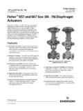
2 Instructions:1. Assembly notes:Input 0 can be optionally pulled high (use 10k resistor in position RPU) or pulled low (use the resistor in positionRPD). Only fit one of the two SIL resistor provides a 10k pull-down to all the other inputs. It is polarised, the end marked with a dot must beat the top of the picaxe requires a supply which is connected via the battery clip pads at the bottom of the PCB. Note thebattery clip can be threaded through the board prior to soldering to generate a stronger ULN2803A output driver can use its own separate power supply (connected top right) or the same supply asthe picaxe chip. To use the same supply a wire link must be soldered in the position Insert a picaxe -20M microcontroller (purchased separately).
3 ONLY USE A or 5V battery pack, not a 9V PP3battery, as the power Note that the outputs on the right of the board are buffered by the darlington driver chip. They are therefore opencollector outputs (outputs are connected between V+ and the output, not 0V and the output).4. Use the Programming Editor software to develop a control program, and then download the program to the boardby connecting the picaxe download cable (part AXE026 or AXE027).Option 1 - Direct Input/ Output Connection:Some output devices ( Serial LCD) require a direct connection to the picaxe output (rather than the darlingtondriver buffered output). Each input / output of the picaxe chip has a direct connection pad directly beside the leg ofthe chip.
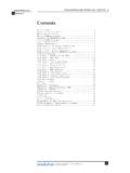
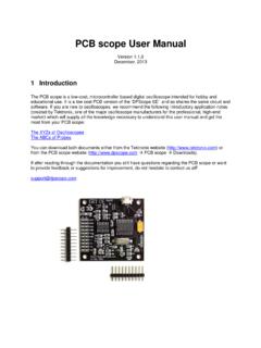
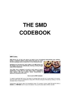
4 The pad marked PZ is designed for connecting a piezo sounder and connects directly to output 1. 2revolutionRevolution Education Ltd. Email: Web: 30/01 Project Board ! " !# $ " % & ' ( )*(+*( , , - ."/ +"0+" , , , , , , ,12 + Circuit Diagram))