Transcription of Control System (ECE411) Lectures 13 & 14
1 Time-Domain AnalysisAnalyzing Simple ControllersControl System (ECE411) Lectures 13 & Azimi, ProfessorDepartment of Electrical and Computer EngineeringColorado State UniversityFall AzimiControl SystemsTime-Domain AnalysisAnalyzing Simple ControllersSteady-State Error AnalysisRemark: For aunity feedback System (H(s) = 1):e(t) =r(t) c(t)E(s) =R(s) C(s) =R(s) R(s)M(s) =E(s) = [1 M(s)]R(s)whereM(s)is the closed loop transfer ,ess= lims 0sE(s) = lims 0s[1 M(s)]R(s)For a unit stepR(s) =1s, we getess= [1 M(0)]Note:The above results could sometimes be used for cases whenH(s)6= 1(tracking error).ExampleGiven a unity feedback System shown below with closed loop transfer functionM(s) =K(s2+2s+2)(s+a), AzimiControl SystemsTime-Domain AnalysisAnalyzing Simple ControllersSteady-State Error Analysis-Cont.(a) findKandasuch thatess= unit ramp input,(b) findessfor unit step (a): First, we find the open-loop transfer functionG(s)fromM(s)using,M(s) =G(s)1 +G(s)=K(s2+ 2s+ 2)(s+a)= G(s) =K(s2+ 2s+ 2)(s+a) K=Ks3+ (a+ 2)s2+ (2a+ 2)s+ (2a K)Now, in order to avoid a Type 0 System which yieldsess for ramp input,2a K= 0 = K= a unit ramp input:ess=1 KvwhereKv= lims sG(s)Thus,ess=1Kv= = Kv= AzimiControl SystemsTime-Domain AnalysisAnalyzing Simple ControllersSteady-State Error (s)inKv= lims sG(s)andKv=23gives,Kv= lims Ks2+ (a+ 2)s+ (2a+ 2)= K2a+ 2=23 Solving forKandausing the above equation andK= 2agivesa= 2, andK= (b): Using the result from part (a).
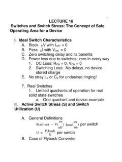
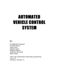
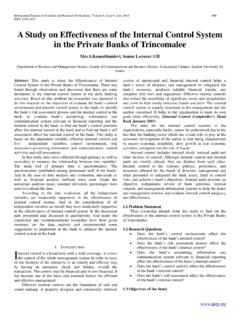
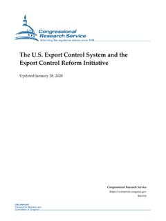
2 G(s) =4s(s2+ 4s+ 6)which is obviously Type 1 System = ess= 0to unit step AzimiControl SystemsTime-Domain AnalysisAnalyzing Simple ControllersTransient AnalysisTransient ResponseTransient response allows for determining whether or not a System is stable and,if so, how stable it is ( relative stability) as well as the speed of responsewhen a step reference input is typical time-domain response of a second order System (closed loop) to a unitstep input is AzimiControl SystemsTime-Domain AnalysisAnalyzing Simple ControllersTransient Definitions:1 Max Overshoot (Mp)Mp=cmax csscsscmax: max value ofc(t),css: steady-state value ofc(t)%max overshoot= 100 MpMpdetermines relative stability: LargeMp less stable2 Delay time (td): Time forc(t)to reach50%of its final time (tr): Time forc(t)to rise from10%to90%of its final time (ts): Time forc(t)to decrease and stay within a specified(typically5%) characteristics: SmallMp, smalltd, quicktrand fastts(cannot beaccomplished simultaneously).
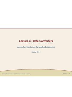
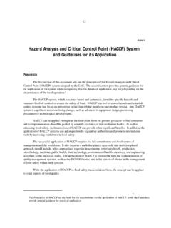
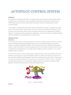
3 AzimiControl SystemsTime-Domain AnalysisAnalyzing Simple ControllersTransient Response of2nd-Order Control SystemConsider a Control System with closed-loop transfer function,M(s) =C(s)R(s)= 2ns2+ 2 ns+ 2n, M(0) = 1 Characteristic Equation : (s) =s2+ 2 ns+ 2n= 0has the following roots,s1,2= n j n 1 2= j These are depicted in the following = ,tan = 1 2 AzimiControl SystemsTime-Domain AnalysisAnalyzing Simple ControllersTransient Response of2nd-Order Control to unit step input (R(s) =1s) isC(s) = 2ns(s2+ 2 ns+ 2n (s+ )2+ 2)Use PFE, time-domain response is found to bec(t) = 1 css+damping e t 1 2sin[ t ] ctr(t), t 0 = n: Damping Factor- Controls the rate of rise time and decay time controls damping and speed of Control oscillations by changing .Can Control damping by changing . AzimiControl SystemsTime-Domain AnalysisAnalyzing Simple ControllersTransient Response of2nd-Order Control System -Cont.
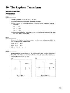
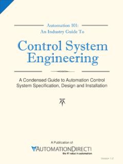
4 = 1/ : Time ConstantLarge = small = signal decays quickly. : Damping Ratio (ratio between actual damping factor and the damping factorfor critically damped ( = 1 = s1,2= n). n: Natural Undamped Frequency ( = 0 = s1,2= j purelyoscillatory with frequency n) = n 1 2: Conditional AzimiControl SystemsTime-Domain AnalysisAnalyzing Simple ControllersTransient Response-Different Damping Cases(a)Underdamped:0< <1,s1,2= n j n 1 2 Characteristics:Small rise time (tr), large overshoot (Mp).(b)Critically Damped: = 1,s1,2= n(repeated real roots)Characteristics:No overshoot, slow/large rise AzimiControl SystemsTime-Domain AnalysisAnalyzing Simple ControllersTransient Response-Different Damping Cases(c)Overdamped: >1s1,2= n n 2 1(two real distinct roots)Characteristics:No overshoot, very large rise time.(d)Undamped (Oscillatory): = 0,s1,2= j AzimiControl SystemsTime-Domain AnalysisAnalyzing Simple ControllersTransient Response-Different Damping Cases(e)Negatively damped (unstable): <0,s1,2= n j n 1 AzimiControl SystemsTime-Domain AnalysisAnalyzing Simple ControllersTransient Response: Performance Measures1.)
5 Peak Time (tmax)To find the peak time (time at which the step response reaches its maximum),we take the derivative of the step response and set it to (t)dt= 0dc(t)dt= e nt 1 2sin [ t ] +e nt 1 2 cos[ t ]Using = n 1 2and trig identities, we can simplify the above equation as:dc(t)dt= n 1 2e ntsin( t), t 0,Now,dc(t)dt= 0 = sin ( t) = 0or whent ( final value)The first condition gives the extrema points (maxima and minima) ofc(t), t=n = t=n n 1 2 The first maximum (Max overshoot) ofc(t)happens forn= 1. Thus,tmax= n 1 AzimiControl SystemsTime-Domain AnalysisAnalyzing Simple ControllersTransient Response-Performance :Although Max and Min ofc(t)occur at periodic interval, the response isNOT periodic due to damping (unless = 0).2. Max Overshoot (Mp)To findMp, we substitutetmaxin expression forc(t). This yields,cmax=c(t)|t=tmax= 1 +e 1 2 Thus, using the fact thatcss= 1, we getMp=cmax 1 =e 1 2Or in percentage,%Max Overshoot= 100e 1 2As can be seen, Max Overshoot is solely a function of.
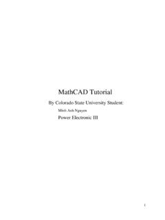
6 Hence, Larger = smallerMp( <1). But this would increase the delay time and rise time asseen ,tr, andtsonly approximate equations can be obtained. These are AzimiControl SystemsTime-Domain AnalysisAnalyzing Simple ControllersTransient Response-Performance Delay Time (td)Fortd, we setc(t) = solve fortd,td 1 + n,0< <1td 1+ + 2 n: wider range of and more Rise Time (tr)tr + n,0< <1tr=1+ + 2 n, wider range of and more Settling Time(ts)ts 4/ nAs can be seen, Small = smallertdandtrbut Range for AzimiControl SystemsTime-Domain AnalysisAnalyzing Simple ControllersAnalyzing Simple Controllers for2ndOrder Systems1. Gain ControllerConsider servo Control System below:Steady State Error Analysis:Loop transfer function:G(s) =Ks(Js+B)= Type 1= ess= 0forr(t) =us(t)For a unit ramp inputess=1 KvandKv= lims 0sG(s)H(s) =KBThus,essto unit ramp= ess=BKwhich implies SmallessRequiresLarge AzimiControl SystemsTime-Domain AnalysisAnalyzing Simple ControllersAnalyzing Simple Controllers for2ndOrder Analysis.
7 The closed-loop transfer functionM(s) =G(s)1+G(s)=Ks(sJ+B)1+Ks(Js+B)=K/Js2+Bs/ J+K/JComparing with standard case,M(s) = 2ns2+2 n+ 2n= n= K/Jand2 n =B/J= =B2 KJSinceBandJcannot be tweaked (motor parameters), LargeK= Reduced = largeMp= less , a simple gain controller (K) won t produce desirable steady-state andtransient behavior as a compromise between small steady state error and goodrelative stability and fast response cannot be AzimiControl SystemsTime-Domain AnalysisAnalyzing Simple ControllersAnalyzing Simple Controllers for2ndOrder Proportional-Derivative Controller (PD)Controller transfer functionGc(s) =KP+KDs, whereKPis the proportionalconstant, andKDis the derivative State Error Analysis:Loop transfer function:G(s) =Gc(s)Gp(s) =KP+KDss(Js+B)= Still Type 1= ess= 0forr(t) =us(t)For a unit ramp inputess=1 KvandKv= lims 0sG(s)H(s) =KPB= ess= it is possible to makeessto a unit ramp as small as possible by increasingproportional AzimiControl SystemsTime-Domain AnalysisAnalyzing Simple ControllersAnalyzing Simple Controllers for2ndOrder Analysis:The closed-loop transfer functionM(s) =Gc(s)Gp(s)1+Gc(s)Gp(s)=(KP+KDs)/Js2+(B+ KD)sJ 2 n+KPJ 2nAgain, comparing with standard case,M(s) = 2ns2+2 n+ 2n= n= KPJand2 n =(B+KD)J= =B+KD2 KPJThus, we can choose:(a) LargeKPfor smallessto unit ramp, and(b) AppropriateKDto < < , PD controller adds a zero ats= KP/KDwhich could have animpact in changing the shape of the response to unit step.
8 Additionally, PDcontroller is susceptible to noise and difficult to AzimiControl SystemsTime-Domain AnalysisAnalyzing Simple ControllersAnalyzing Simple Controllers for2ndOrder Tachometer ControlUsing1s(Js+B)= (1Js+B)(1s), we design a rate feedback (tachometer) Control as , the above block diagram can be reduced to the typically usedtachometer Control AzimiControl SystemsTime-Domain AnalysisAnalyzing Simple ControllersAnalyzing Simple Controllers for2ndOrder State Error Analysis:Loop transfer function:G(s)H(s) =K(1+Kts)s(Js+B)= Still Type 1= ess= 0forr(t) =us(t)For a unit ramp inputess=1 KvandKv= lims 0sG(s)H(s) =KB= ess= it is possible to makeessto a unit ramp as small as possible by Analysis:The closed-loop transfer functionM(s) =KJs2+(B+KKt)Js+KJComparing with standard case,M(s) = 2ns2+2 n+ 2n= n= KJand2 n =(B+KKt)J= =B+KKt2 AzimiControl SystemsTime-Domain AnalysisAnalyzing Simple ControllersAnalyzing Simple Controllers for2ndOrder , we can choose:(a) Large GainKfor smallessto unit ramp, and(b) AppropriateKtto < < :Tachometer Control doesn t have the same issues of the PD , used widely for servo : For the tach Control System below, findKandKtsuch that maxovershoot,Mp, to unit step peak time is 1 second.
9 Then, using thesevalues ofKandKt, / 1 2= = = n 1 2= 1 = n= AzimiControl SystemsTime-Domain AnalysisAnalyzing Simple ControllersAnalyzing Simple Controllers for2ndOrder ,K= 2n= K= , =1+KKt2 K= = Kt= + n= n= AzimiControl Systems