Transcription of CS250 VLSI Systems Design Lecture 8: Memory
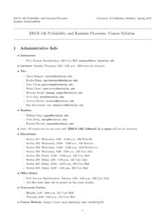
1 Lecture 8, MemoryCS250, UC Berkeley, Fall 2010CS250 vlsi Systems DesignLecture 8: MemoryJohn Wawrzynek, Krste Asanovic,withJohn LazzaroandYunsup Lee (TA)UC BerkeleyFall 2010CS250, UC Berkeley, Fall 2010 Lecture 8, MemoryCMOS BistableCross-coupled inverters used to hold state in CMOS Static storage in powered cell, no refresh neededIf a storage node leaks or is pushed slightly away from correct value, non-linear transfer function of high-gain inverter removes noise and recirculates correct valueTo write new state, have to force nodes to opposite state2DD 1 0 DD 0 1 Flip StateCS250, UC Berkeley, Fall 2010 Lecture 8, MemoryCMOS Transparent LatchLatch transparent (output follows input)
2 When clock is high, holds last value when clock is low3 Optional Input BufferOptional Output BufferDQClkClkClkClkDQClkDQClkSchematic SymbolsTransparent on clock lowTransmission gate switch with both pMOS and nMOS passes both ones and zeros wellCS250, UC Berkeley, Fall 2010 Lecture 8, MemoryLatch Operation4DQ1100 DClock HighLatch TransparentDQ0011 QClock LowLatch HoldingCS250, UC Berkeley, Fall 2010 Lecture 8, MemoryFlip-Flop as Two Latches5 QClkClkClkClkHoldDQClkClkClkClkSampleQDC lkClkSchematic SymbolsThis is how standard cell flip-flops are built(usually with extra in/out buffers) CS250 , UC Berkeley, Fall 2010 Lecture 8, MemorySmall Memories from Stdcell LatchesAdd additional ports by replicating read and write port logic (multiple write ports need mux in front of latch)Expensive to add many ports6 Write Address DecoderRead Address DecoderClkWrite AddressWrite DataRead AddressClkCombinational logic for read port (synthesized)
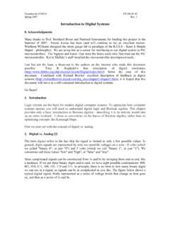
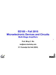
3 Optional read output latchData held in transparent-low latchesWrite by clocking latchCS250, UC Berkeley, Fall 2010 Lecture 8, Memory6-Transistor SRAM (Static RAM)7 Large on-chip memories built from arrays of static RAM bitcells, where each bit cell holds a bistable (cross-coupled inverters) and two access clocking and access logic factored out into peripheryBitBitWordlineCS250, UC Berkeley, Fall 2010 Lecture 8, MemoryIntel s 22nm SRAM cell8!"#$%&''(&&%)*%!+,-%."/$%012#!"!#$% &'$()%*+,%)' ,)*%/012%3,..%(4%5678(49%3(73&(*)%7,:67* ,;%*6%;-*, um2 SRAM cell for high density um2 SRAM cell for low voltage applications[Bohr, Intel, Sept 2009] CS250 , UC Berkeley, Fall 2010 Lecture 8, MemoryGeneral SRAM Structure9 Address Decode and Wordline DriverDifferential Read Sense AmplifiersDifferential Write DriversBitline PrechargersAddressWrite DataRead DataUsually maximum of 128-256 bits per row or columnClkClkWrite EnableCS250, UC Berkeley, Fall 2010 Lecture 8, MemoryAddress Decoder Structure10A1A0A3A22.)
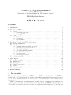
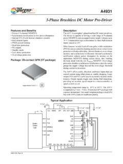
4 4 PredecodersClocked Word Line EnableAddressWord Line 0 Word Line 1 Word Line 15 Unary 1-of-4 encodingCS250, UC Berkeley, Fall 2010 Lecture 8, MemoryRead Cycle111) Precharge bitlines and senseamp1)2) Pulse wordlines, develop bitline differential voltage2)Bitline differentialClkBit/BitWordlineSenseData/ Data3) Disconnect bitlines from senseamp, activate sense pulldown, develop full-rail data signals3)Full-rail swingPulses generated by internal self-timed signals, often using replica circuits representing critical pathsClkSenseDataDataFrom DecoderWordline ClockPrechargersSense AmpStorage CellsBitBitOutput Set-Reset LatchCS250, UC Berkeley, Fall 2010 Lecture 8, MemoryWrite Cycle121) Precharge bitlines1)ClkBit/BitWordline2) Open wordline, pull down one bitline full rail2)ClkWrite DataFrom DecoderWordline ClockPrechargersStorage CellsBitBitWrite EnableWrite-enable can be controlled on a per-bit level.
5 If bit lines not driven during write, cell retains value (looks like a read to the cell). CS250 , UC Berkeley, Fall 2010 Lecture 8, MemoryColumn-Muxing at Sense Amps13 Sel1 ClkSel0 From DecoderWordline ClockSense AmpDifficult to pitch match sense amp to tight SRAM bit cell spacing so often 2-8 columns share one sense amp. Impacts power dissipation as multiple bitline pairs swing for each bit , UC Berkeley, Fall 2010 Lecture 8, MemoryBuilding Larger Memories14 Bit cellsDecI/OBit cellsI/OBit cellsDecBit cellsBit cellsDecI/OBit cellsI/OBit cellsDecBit cellsBit cellsDecI/OBit cellsI/OBit cellsDecBit cellsBit cellsDecI/OBit cellsI/OBit cellsDecBit cellsLarge arrays constructed by tiling multiple leaf arrays, sharing decoders and I/O.
6 Sense amp attached to arrays above and belowLeaf array limited in size to 128-256 bits in row/column due to RC delay of wordlines and bitlinesAlso to reduce power by only activating selected sub-bankIn larger memories, delay and energy dominated by I/O wiringCS250, UC Berkeley, Fall 2010 Lecture 8, MemoryAdding More Ports15 BitABitAWordlineAWordlineBBitBBitBWordli neRead BitlineDifferential Read or Write portsOptional Single-ended Read portCS250, UC Berkeley, Fall 2010 Lecture 8, MemoryMemory CompilersIn ASIC flow, Memory compilers used to generate layout for SRAM blocks in designOften hundreds of Memory instances in a modern SoCMemory generators can also produce built-in self-test (BIST)
7 Logic, to speed manufacturing testing, and redundant rows/columns to improve yieldCompiler can be parameterized by number of words, number of bits per word, desired aspect ratio, number of sub banks, degree of column muxing, , delay, and energy consumption complex function of Design parameters and generation algorithmWorth experimenting with Design spaceUsually only single read or write port SRAM and one read and one write SRAM generators in ASIC library16CS250, UC Berkeley, Fall 2010 Lecture 8, MemorySmall Memories17 Compiled SRAM arrays usually have a high overhead due to peripheral circuits, BIST, redundancy.
8 Small memories are usually built from latches and/or flip-flops in a stdcell flowCross-over point is usually around 1K bits of storageShould try Design both waysCS250, UC Berkeley, Fall 2010 Lecture 8, MemoryMemory Design Patterns18CS250, UC Berkeley, Fall 2010 Lecture 8, MemoryMultiport Memory Design PatternsOften we require multiple access ports to a common memoryTrue Multiport MemoryAs describe earlier in Lecture , completely independent read and write port circuitryBanked Multiport MemoryInterleave lesser-ported banks to provide higher bandwidthStream-Buffered Multiport MemoryUse single wider access port to provide multiple narrower streaming portsCached Multiport MemoryUse large single-port main Memory , but add cache to service 19CS250, UC Berkeley, Fall 2010 Lecture 8, MemoryTrue Multiport MemoryProblem: Require simultaneous read and write access by multiple independent agents to a shared common.
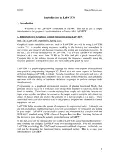
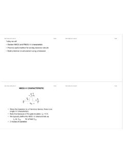
9 Provide separate read and write ports to each bit cell for each requesterApplicability: Where unpredictable access latency to the shared Memory cannot be : High area, energy, and delay cost for large number of ports. Must define behavior when multiple writes on same cycle to same word ( , prohibit, provide priority, or combine writes).20CS250, UC Berkeley, Fall 2010 Lecture 8, MemoryTrue Multiport Example: Itanium-2 RegfileIntel Itanium-2 [Fetzer et al, IEEE JSSCC 2002]211434 IEEE JOURNAL OF SOLID-STATE CIRCUITS, VOL. 37, NO. 11, NOVEMBER 2002 Fig.
10 2. Register file circuit and timing 3. Double-pumped pulse clock generator circuit and timing of logic. To prevent pulse degradation, a pulsewidth-con-trol feedback delay is inserted between the decoder and the wordline. The word line muxing, internal to the register, capturespulses during the write phase of the system clock and holds thewrite signal at high value until the end of the phase, giving thewrite mechanism more than a pulse width to write data into theregister. Since writes are single ended through a nFET pass gate,one leg of the cell is floated using a virtual ground, which im-proves timing and cell writeability.