Transcription of “D” Series - STA-RITE
1 1362 1094 ASBNF D SeriesInstallation/Operation/PartsFor further operating, installation, or maintenance assistance: Call 1-888-782-7483 OWNER S MANUALSelf-Priming Centrifugal Pumps 2013 Pentair Ltd. All Rights Reserved. S976 (REV 01/14/13)293 WRIGHT STREET, DELAVAN, WI 53115 : 888-782-7483 Safety 2 READ AND FOLLOW SAFETY INSTRUCTIONS!This is the safety alert symbol. When you see this symbol on your pump or in this manual , look for one of the following signal words and be alert to the potential for personal injury: warns about hazards that will cause serious personal injury, death or major property if ignored. warns about hazards that can cause serious personal injury, death or major property damage if ignored. warns about hazards that will or can cause minor personal injury or property damage if label NOTICE indicates special instructions which are important but not related to read and follow all safety instructions in this manual and on safety labels in good condition.
2 Replace missing or damaged safety workshops childproof; use padlocks and master switches; remove Proposition 65 Warning This product and related accessories contain chemicals known to the State of California to cause cancer, birth defects or other reproductive SAFETY Do not touch an operating motor. Modern motors are designed to operate at high temperatures. To avoid burns when servicing pump, allow it to cool for 20 minutes after shut-down before not allow pump or any system component to freeze. To do so will void water only with this inspect pump and system safety glasses at all times when working on work area clean, uncluttered and properly lighted; store properly all unused tools and visitors at a safe distance from the work areas. Pump body may explode if used as a booster pump unless relief valve capable of passing full pump flow at 75 psi is pressure! Install pressure relief valve in discharge all pressure on system before working on any voltage.
3 Can shock, burn, or cause pump before connecting to power supply. Disconnect power before working on pump, motor or tank. Wire motor for correct voltage. See Electri cal section of this manual and motor nameplate. Ground motor before connecting to power supply. Meet National Electrical Code, Canadian Elec tri cal Code, and local codes for all wiring. Follow wiring instructions in this manual when connecting motor to power of Contents 3 Thank you for purchasing a top quality, factory tested Safety ..4-5 Electrical ..6-7 Service ..8-10 Repair Parts ..11-12 Limited WarrantySTA-RITE warrants to the original consumer purchaser ( Purchaser or You ) of the products listed below, that they will be free from defects in material and workmanship for the Warranty Period shown below. ProductWarranty PeriodWater Systems Products jet pumps, small centrifugal pumps, submersible pumps and related accessorieswhichever occurs first: 12 months from date of original installation, or 18 months from date of manufacturePro-Source Composite Tanks5 years from date of original installationPro-Source Steel Pressure Tanks5 years from date of original installationPro-Source Epoxy-Lined Tanks3 years from date of original installationSump/Sewage/Effluent Products12 months from date of original installation, or 18 months from date of manufactureOur warranty will not apply to any product that, in our sole judgement, has been subject to negligence, misapplication, improper installation, or improper maintenance.
4 Without limiting the foregoing, operating a three phase motor with single phase power through a phase converter will void the warranty. Note also that three phase motors must be protected by three-leg, ambient compensated, extra-quick trip overload relays of the recommended size or the warranty is only remedy, and STA-RITE s only duty, is that STA-RITE repair or replace defective products (at STA-RITE s choice). You must pay all labor and shipping charges associated with this warranty and must request warranty service through the installing dealer as soon as a problem is discovered. No request for service will be accepted if received after the Warranty Period has expired. This warranty is not SHALL NOT BE LIABLE FOR ANY CONSEQUENTIAL, INCIDENTAL, OR CONTINGENT DAMAGES FOREGOING WARRANTIES ARE EXCLUSIVE AND IN LIEU OF ALL OTHER EXPRESS AND IMPLIED WARRANTIES, INCLUDING BUT NOT LIMITED TO THE IMPLIED WARRANTIES OF MERCHANTABILITY AND FITNESS FOR A PARTICULAR PURPOSE.
5 THE FOREGOING WARRANTIES SHALL NOT EXTEND BEYOND THE DURATION EXPRESSLY PROVIDED states do not allow the exclusion or limitation of incidental or consequential damages or limitations on the duration of an implied warranty, so the above limitations or exclusions may not apply to You. This warranty gives You specific legal rights and You may also have other rights which vary from state to Limited Warranty is effective June 1, 2011 and replaces all undated warranties and warranties dated before June 1, INDUSTRIES 293 Wright Street Delavan, WI 53115 Phone: 1-888-782-7483 Fax: 1-800-426-9446 Web Site: 4 Support suction pipeas requiredSupport discharge pipe as requiredAs closeas possible4 x "D"minimumPipe diameter "D"at least as large aspump suction connectionImportant:All connections mustbe air tightSolid, levelbasePrimingPlugGateValveUnionDischa rge to serviceRecommended pump suctionand discharge connectionsNot recommended pump suctionand discharge connections Elbow immediately in front of pump diameter "D"insufficient sizePipe submergedless than 4 x "D"will cause vortexingLong suctionrunValveUnsupportedPipeMisaligned pipe causes air leaks.
6 High spots along the suction line result in air suction flange adapterkeeps suction water level above impeller eye to aid priming. Use of excess fittingsmeans potential air leaksStraight run, short aspossible but at least 6times pipe diameter ("D");slope is down going away from 0894 Some models have topdischarge; these requirea priming tee. On the discharge avoid:Quick closing turns in piping 1 Figure 2 Installation 5 LOCATION OF UNITL ocate the pump as near the liquid source as possible, using a short, direct suction pipe. Keep the static suction lift (vertical distance between the cen-ter line of the pump and the liquid level) to a minimum. Mount the pump on a solid, level foundation, which provides a rigid and vibration-free sup-port. It should be located where the unit is readily accessible for service and maintenance. The pump should be protected against flooding and excessive suction and discharge piping should be independently supported at a point near the pump to avoid strains being placed on the pump.
7 Start all piping at pump to avoid strains left by a gap at last PIPINGThe suction pipe must be kept free of leaks. The suction pipe must have a gradual slope upward to the pump. Avoid any fittings which may cause an air trap. On units that have a suction fitting, a check valve is a built-in fea-ture and no foot valve is PIPINGA gate valve and union should be installed in the discharge line. For remov-al of the pump for service, close the gate valve, and disconnect at 6 Disconnect power at service panel be fore connecting motor. Single phase motors come factory wired for 230 volt operation. Do not alter wiring in single phase motors. Match motor voltage to power supply voltage. Do not connect three phase motors to single phase power supply or single phase motors to three phase power supply. Ground motor before connecting to electrical power supply. Failure to ground motor can cause severe or fatal electrical shock hazard. Do not ground to a gas supply line.
8 To avoid dangerous or fatal electrical shock, turn OFF power to motor before working on electrical connections. Supply voltage must be within 10% of nameplate voltage. Incorrect voltage can cause fire or seriously damage motor and voids warranty. If in doubt consult a licensed electrician. Use wire size specified in Wiring Chart. If possible, connect pump to a separate branch circuit with no other appliances on 1. Install, ground, wire and maintain this pump in ac cordance with your local electrical code and all other codes and ordinances that apply. Consult your local building inspector for local code 2. Ground the pump permanently using a wire of size and type speci-fied by local or National Electrical Code. Do not ground to a gas supply 3. Connect ground wire first. Connect to ground first, then to green grounding terminal provided (identified as GRD or ). Make ground connection to this terminal. Do not con-nect motor to electrical power supply until unit is permanently grounded; otherwise serious or fatal electrical shock hazard may be 4.
9 For best ground connection, connect to a grounded lead in the service panel or to a metal underground water pipe or well casing at least 10 ft. long. If plastic pipe or insulated fittings are used, run ground wire directly to the metal well casing or use ground elec-trode furnished by the power voltage. Can shock, burn, or cause pump before connecting to power 7 Before using pump, check your motor nameplate for volt-age. Your electric supply voltage and the stamped nameplate voltage must agree. Motors stamped 200 volts only or 230 volts only, must be used with that voltage only. Motors stamped with two voltages (for example 230/460 volts), may be used with either supply voltage. For these motors check con-nections against wiring diagram on motor nameplate and make any chang-es necessary to agree with your supply voltage. If in doubt, call a licensed electrician. Incorrect voltage will cause serious damage to the models are equipped with three phase motors.
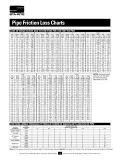
10 Three phase motors require magnetic check motors for proper rotation: The shaft can be seen through the motor - pump adapter bracket. A mark can be made on the shaft to make it easier to notice rotation. Jog the motor (start it briefly) and note the rota-tion. It should rotate clockwise when viewed from the motor-end. If rotation is not clockwise, see motor nameplate for hookup information. BE SURE power is off to the motor when working on electrical connections. Motor normally operates at high temperature and will be too hot to touch. Before handling pump or motor, stop motor and allow it to cool for 20 I Recommended Wire and Fuse Sizes DIAMETER IN FEET FROM MOTOR TO METER BRANCH 0 51 101 201 301 401 MAX. FUSE* TO TO TO TO TO TO MOTOR LOAD RATING 50 100 200 300 400 500 HP PHASE VOLTS AMPS AMPS WIRE SIZE 3 1 230 25 12 12 12 10 8 8 3 1 200 30 10 10 10 10 8 8 3 3 200 15 14 14 14 12 10 10 3 3 230 15 14 14 14 12