Transcription of Data Converters - www-inst.eecs.berkeley.edu
1 EECS 247 Lecture 11: data Converters 2004 Page 1EE247 Lecture 11 data ConvertersEECS 247 Lecture 11: data Converters 2004 Page 2 Material Covered in EE247 Filters Continuous-time filters Biquads & ladder type filters Opamp-RC, Opamp-MOSFET-C, gm-C filters Automatic frequency tuning Switched capacitor (SC) filters data Converters D/A converter architectures A/D converter Nyquist rate ADC-Flash, Pipeline ADCs,.. Oversampled Converters Self-calibration techniques Systems utilizing analog/digital interfaces Wireline communication systems-ISDN, Wireless communication systems-Wireless LAN, Cellular telephone,.. Disk drive electronics Fiber-optics systems EECS 247 Lecture 11: data Converters 2004 Page 3 data converter Topics Basic Operation of data Converters Uniform sampling and reconstruction Uniform amplitude quantization Characterization and Testing Common ADC/DAC Architectures Selected Topics in converter Design Practical Implementations Desensitization to Analog Circuit Non-Idealities Figures of Merit and Performance TrendsEECS 247 Lecture 11: data Converters 2004 Page 4 Suggested Reference Texts R.
2 V. d. Plassche, CMOS Integrated Analog-to-Digital and Digital-to-Analog Converters , 2nd ed., Kluwer, 2003. B. Razavi, data Conversion System Design,IEEE Press, 1995. S. Norsworthyet al (eds), Delta-Sigma data Converters ,IEEE Press, treatment of oversampledconverters including stability, tones, bandpassconverters. J. G. Proakis, D. G. Manolakis, Digital Signal Processing, Prentice Hall, 247 Lecture 11: data Converters 2004 Page 5 ConverterApplicationsEECS 247 Lecture 11: data Converters 2004 Page 6 Example: Typical Cell PhoneContains in integrated form: 4 Rx filters 4 Tx filters 4 Rx ADCs 4 Tx DACs 3 Auxiliary ADCs 8 Auxiliary DACsTotal: Filters 8 ADCs 7 DACs 12 Dual Standard, I/QAudio, Tx/Rx powercontrol, Battery chargecontrol, display, ..EECS 247 Lecture 11: data Converters 2004 Page 7 data converter Basics DSP is wonderful, Real world signals are analog: Continuous time Continuous amplitude DSP can only process: Discrete time Discrete amplitude Need for data conversion from analog to digital and digital to analogAnalog PostprocessingD/AConversionDSPA/D ConversionAnalog PreprocessingAnalog InputAnalog 247 Lecture 11: data Converters 2004 Page 8A/D & D/A ConversionA/D ConversionD/A ConversionEECS 247 Lecture 11: data Converters 2004 Page 9 data Converters Stand alone data Converters Used in variety of systems Example: Analog Devices AD9235 12bit/ 65Ms/s ADC-Applications.
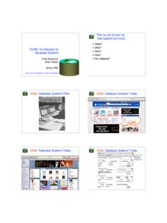
3 Ultrasound equipment IF sampling in wireless receivers Hand-held scopemeters Low cost digital oscilloscopes Embedded data Converters Cost, reliability, and performance integration of data conversion interfaces along with DSPs Main issues Feasibility of integrating sensitive analog functions in a technology optimized for digital performance Down scaling of supply voltage Interference & spurious signal pick-up from on-chip digital circuitry Portable applications dictate low power consumptionEECS 247 Lecture 11: data Converters 2004 Page 10D/A converter Transfer Characteristic For an ideal digital-to-analog converter with uniform, binary digital encoding & a unipolar output range from 0 to VFSNN0 FSi1i1 NiibiVVbi2,bi0or12== == = b2 b3bnV0 FSwhereN#ofbitsVfullscaleoutputstepsize= = =()0 FSFSNNote:VVbi1,alli11V2= = = MSBLSB()0210 ++EECS 247 Lecture 11: data Converters 2004 Page 11 Ideal D/A Transfer Characteristic Ideal DAC introduces no error!
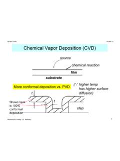
4 One-to-one mapping from input to output001 010 011 100 101 110 111 Step Height (1 LSB= )Ideal ResponseDigital InputCodeAnalog OutputVFS VFS /2 VFS /8 EECS 247 Lecture 11: data Converters 2004 Page 12A/D converter Transfer Characteristic For an ideal analog-to-digital converter with uniform, binary digital encoding & a unipolar input range for 0 to b2 b3bnVinFSwherem#ofbitsVfullscaleoutputst epsize== =()FSFSmNote:DVbi1,alli11V2 = MSBLSBA/DEECS 247 Lecture 11: data Converters 2004 Page 13 Ideal A/D Transfer Characteristic Ideal ADC introduces error (+-1/2 ) = VFS/2m m= # of bits This error is called ``quantization error``111110101 1000110100010001 LSBD igital OutputAnalog input 2 3 4 5 6 7 EECS 247 Lecture 11: data Converters 2004 Page 14 data converter Performance Metrics data Converters are typically characterized by static, time-domain, & frequency domain performance metrics : Static Monotonicity Offset Gain error Differential nonlinearity (DNL) Integral nonlinearity (INL) Dynamic Delay, settling time Aperture uncertainty Distortion-harmonic content Signal-to-noise ratio (SNR), Signal-to-(noise+distortion) ratio (SNDR) Idle channel noise Dynamic range & spurious-free dynamic range (SFDR)EECS 247 Lecture 11: data Converters 2004 Page 15 What is a discrete time signal?
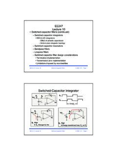
5 QA signal that changes only at discrete time instances? qA continous time signal multiplied with a train of infinitely narrow unit pulses?qA vector whose element indices correspond to discrete instances in time?qAll of the above?[ ..]timeEECS 247 Lecture 11: data Converters 2004 Page 16 Discrete Time Signals A sequence of numbers (or vector) with discrete index time instants Intermediate signal values not defined(not the same as equal to zero!) Mathematically convenient, non-physical We will use the term "sampled data "forrelated signals that occur in real, physical interface circuitsEECS 247 Lecture 11: data Converters 2004 Page 17 Typical Sampling ProcessCT SD DTContinuousTimeSampled data ( T/H signal)ClockDiscrete TimetimePhysicalSignals"MemoryContent"EE CS 247 Lecture 11: data Converters 2004 Page 18 Uniform Sampling Samples spaced T seconds in time Sampling Period T Sampling Frequency fs=1/T Problem: Multiple continuous time signals can yield exactly the same discrete time signal (aliasing)y(kT)=y(k)t= 1T 2T 3T4T5T6T.
6 K= 1 2 3456 ..EECS 247 Lecture 11: data Converters 2004 Page 19 SummaryData Converters ADC/DACs need to sample/reconstruct to convert from continuous time to discrete time signals and back We distinguish between purely mathematical discrete time signals and "sampled data signals" that carry information in actual circuits Question: How do we ensure that sampling/reconstruction preserves informationEECS 247 Lecture 11: data Converters 2004 Page 20 Aliasing The frequencies fxand Nfs fx, N integer,are indistinguishable in the discrete time domain Undesired frequency interaction and translation due to sampling is called aliasing If aliasing occurs, no signal processing operation downstream of the sampling process can recover the original continuous time signal! Let's look at this in the frequency 247 Lecture 11: data Converters 2004 Page 21 Sampling Sine Wavesfs= 1/Ty(nT)timeTime -finfs + finVoltageFrequency domainEECS 247 Lecture 11: data Converters 2004 Page 22 Frequency Domain scenariobefore samplingSignal scenarioafter sampling DT Signals @nfS fmax__signalfold back into band of interest Aliasingfs 247 Lecture 11: data Converters 2004 Page 23 Aliasing Multiple continuous time signals can produce identical series of sampled voltages The folding back of signals from nfS fsigdown to ffinis called aliasing Sampling theorem: fs> 2fmax_Signal If aliasing occurs, no signal processing operation downstream of the sampling process can recover the original continuous time signal EECS 247 Lecture 11: data Converters 2004 Page 24 Brick Wall Anti-Aliasing 247 Lecture 11: data Converters 2004 Page 25 How to Avoid Aliasing Must obey sampling theorem.
7 Fmax_Signal< fs/2 Two fast enough to cover all spectral components, including "parasitic" ones outside band of fmax_Signalthrough filteringEECS 247 Lecture 11: data Converters 2004 Page 26 How to Avoid domainfsfAmplitudefin2fsFrequency domain1-Push sampling frequency to x2 of the highest freq. Oversampledconverters almost!2-Pre-filter signal to eliminate signals above 1/2 sampling frequency-then samplefs /2fs_newEECS 247 Lecture 11: data Converters 2004 Page 27 Practical Anti-Aliasing Filter Practical filter: Nonzero "transition band" In order to make this work, we need to sample faster than 2x the signal bandwidth "Oversampling" 247 Lecture 11: data Converters 2004 Page 28 Practical Anti-Aliasing 247 Lecture 11: data Converters 2004 Page 29 How much Oversampling? Tradeoff: Sampling speed vs. filter orderMaximum Aliasing Dynamic Rangefs/2fmaxFilter Order[R. v. d. Plassche, CMOS Integrated Analog-to-Digital and Digital-to-Analog Converters , 2nd ed.]
8 , ]EECS 247 Lecture 11: data Converters 2004 Page 30 data ConverterClassification fs> 2fmax Nyquist Sampling "Nyquist Converters " Actually always slightly oversampled fs>> 2fmax Oversampling "Oversampled Converters " Anti alias filtering is often trivial Oversampling is also used to reduce quantization noise, see later in the fs< 2fmax Undersampling (sub-sampling)EECS 247 Lecture 11: data Converters 2004 Page 31 Sub-Sampling Sampling at a rate less than Nyquist rate aliasing For signals centered @ an intermediate frequency Not destructive! Sub-sampling can be exploited to mix a narrowband RF or IF signal down to lower FilterEECS 247 Lecture 11: data Converters 2004 Page 32 Where Are We Now? We now know how to preserve signal information in CT DT transition Howdo we go back from DT CT?Analog PostprocessingD/AConversionDSPA/D ConversionAnalog PreprocessingAnalog InputAnalog (+Quantization)EECS 247 Lecture 11: data Converters 2004 Page 33 Ideal Reconstruction Unfortunately not all that = =kkTtgkxtx)()()(BtBttg 2)2sin()(= The DSP books tell us: x(k)x(t)EECS 247 Lecture 11: data Converters 2004 Page 34 Zero-Order Hold Reconstruction How about just creating a staircase, hold each discrete time value until new information becomes available What does this do the frequency content of the signal?
9 Let's analyze this in two dataafter ZOHEECS 247 Lecture 11: data Converters 2004 Page 351) DT CT: Infinite Zero PaddingDT sequencef/fsTime DomainFrequency paddedDT :CT Signal!.. 247 Lecture 11: data Converters 2004 Page 362) Effect of HoldPulse Usubg the Fourier transform of a rectangular impulse we get:..TpTsppspfTfTTTfH )sin()(=EECS 247 Lecture 11: data Converters 2004 Page 37 Hold Pulse Tp= (H(f))ppspfTfTTTfH )sin(|)(|=EECS 247 Lecture 11: data Converters 2004 Page 38 Hold Pulse Tp= (H(f))ppspfTfTTTfH )sin(|)(|=EECS 247 Lecture 11: data Converters 2004 Page 39 ZOH Spectral DistortionContinuous Time Pulse Train SpectrumZOH Transfer Function("Sinc Distortion")ZOH output, Spectrum of Staircase 247 Lecture 11: data Converters 2004 Page 40 Smoothing FilterAgain: A brick wall filter would be nice Oversampling helps to reduce filter 247 Lecture 11: data Converters 2004 Page 41 Summary Sampling theorem fs> 2fmax, usually dictates anti-aliasing filter If theorem is met, CT signal can be recovered from DT without loss of information ZOH and smoothing filter reconstruct CT from DT signal Oversampling helps reduce order & complexity of anti-aliasing & smoothing filtersEECS 247 Lecture 11.
10 data Converters 2004 Page 42 Next Topic Done with "Quantization in time" Next: Quantization in amplitudeAnalog PostprocessingD/AConversionDSPA/D ConversionAnalog PreprocessingAnalog InputAnalog (+Quantization)SmoothingFilterD/A+ZOHEEC S 247 Lecture 11: data Converters 2004 Page 43 AmplitudeQuantization Amplitude quantization quantization noise Static ADC/DAC performance measures Offset Gain INL DNLEECS 247 Lecture 11: data Converters 2004 Page 44 Ideal ADC ("Quantizer") Quantization step (= 1 LSB) N = 3 Bits Full-scale input .. ( ) Quantization error:bounded by /2 .. + /2for inputs within full-scale range-101234567801234567 Digital Output CodeA/D Characteristics [1]ADC characteristicsideal error [LSB]ADC Input Voltage [1/ ]+ q(Vin)VinDoutADC ModelEECS 247 Lecture 11: data Converters 2004 Page 45 Quantization Error PDF Uniformlydistributed from /2 .. + /2 provided that Busy input Amplitude is many LSBs No overload Not Gaussian!