Transcription of DATA SHEET SMP1304 Series: Low-Distortion …
1 DATA SHEET . SMP1304 series : Low-Distortion Attenuator Plastic Packaged PIN Diodes Applications TV distribution Attenuator circuits Features Low-Distortion design Frequency range from 5 MHz to >2 GHz Designed for base station applications Configured for PI and TEE attenuators Packages rated MSL1 @ 260 C per JEDEC J-STD-020. Description The SMP1304 series of plastic packaged, surface mountable, low Skyworks GreenTM products are compliant with capacitance ( pF) silicon PIN diodes is designed for attenuator all applicable legislation and are halogen-free. applications from 5 MHz to beyond 2 GHz. For additional information, refer to Skyworks The thick 100 m I region of these PIN diodes makes them very De nition of GreenTM, document number attractive for use in Low-Distortion PI and TEE attenuators SQ04 0074. commonly found in TV distribution applications. The 1 s typical carrier lifetime of these diodes results in a resistance of 20 maximum at 1 mA and 7 maximum at 10 mA.
2 The SMP1304 series is available in a selection of plastic packages: as a single diode in small footprint and SC-79. packages, and in a variety of configurations in an SOT-23. package. The SMP1304 -027 is available in an SOT-5 package as a four-diode array designed for insertion in commonly used four- diode PI attenuator circuits. Table 1 describes the various packages and marking of the SMP1304 series . Skyworks Solutions, Inc. Phone [781] 376-3000 Fax [781] 376-3100 200044Q Skyworks Proprietary Information Products and Product Information are Subject to Change Without Notice July 1, 2016 1. DATA SHEET SMP1304 series . Table 1. SMP1304 series Packaging and Marking series Pair Reverse series Pair PI Single SC-79. SOT-23 SOT-23 SOT-5. Green . SMP1304 -005LF SMP1304 -006LF SMP1304 -027LF SMP1304 -079LF. Green Green Green Marking: Cathode and C4. Marking: RG2 Marking: RG8 Marking: RGM. LS = nH LS = nH LS = nH LS = nH. The Pb-free symbol or LF in the part number denotes a lead-free, RoHS-compliant package unless otherwise noted as Green.
3 Tin/lead (Sn/Pb). packaging is not recommended for new designs. Electrical and Mechanical Specifications Package and Handling Information The absolute maximum ratings of the SMP1304 series are Instructions on the shipping container label regarding exposure to provided in Table 2. Electrical specifications are provided in moisture after the container seal is broken must be followed. Table 3. Resistance versus temperature measurements are Otherwise, problems related to moisture absorption may occur provided in Table 4. when the part is subjected to high temperature during solder Typical performance characteristics of the SMP1304 series are assembly. illustrated in Figures 1 to 4. Package dimensions are shown in The SMP1304 series is rated to Moisture Sensitivity Level 1. Figures 5 to 9 (odd numbers), and tape and reel dimensions are (MSL1) at 260 C. It can be used for lead or lead-free soldering. provided in Figures 6 to 10 (even numbers). For additional information, refer to the Skyworks Application Note, Solder Reflow Information, document number 200164.
4 Care must be taken when attaching this product, whether it is done manually or in a production solder reflow environment. Production quantities of this product are shipped in a standard tape and reel format. Skyworks Solutions, Inc. Phone [781] 376-3000 Fax [781] 376-3100 2 July 1, 2016 Skyworks Proprietary Information Products and Product Information are Subject to Change Without Notice 200044Q. DATA SHEET SMP1304 series . Table 2. SMP1304 series Absolute Maximum Ratings1. Parameter Symbol Minimum Maximum Units Reverse voltage VR 200 V. Power dissipation @ 25 C lead temperature PD 250 mW. Storage temperature TSTG 65 +150 C. Operating temperature TA 65 +150 C. Electrstatic discharge: ESD. Human Body Model (HBM), Class 1C 1000 V. 1 Exposure to maximum rating conditions for extended periods may reduce device reliability. There is no damage to device with only one parameter set at the limit and all other parameters set at or below their nominal value. Exceeding any of the limits listed here may result in permanent damage to the device.
5 ESD HANDLING: Although this device is designed to be as robust as possible, electrostatic discharge (ESD) can damage this device. This device must be protected at all times from ESD when handling or transporting. Static charges may easily produce potentials of several kilovolts on the human body or equipment, which can discharge without detection. Industry-standard ESD handling precautions should be used at all times. Table 3. SMP1304 series Electrical Specifications1. (TA = +25 C, Unless Otherwise Noted). Parameter Symbol Test Condition Typical Max Units Reverse current IR VR = 200 V 10 A. Capacitance2 CT f = 1 MHz, V = 30 V pF. Resistance RS f = 100 MHz I = 1 mA 40 50 . I = 10 mA 7 . I = 100 mA 2 . Forward voltage VF IF = 10 mA V. Carrier lifetime Tl IF = 10 mA 1 s I region width 100 m 1 Performance is guaranteed only under the conditions listed in this table. 2 The SMP1304 -027 maximum capacitance is pF. Table 4. Resistance vs Temperature @ 100 MHz IF RS @ 55 C RS @ 15 C RS @ +25 C RS @ +65 C RS @ +100 C.
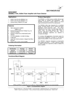
6 (mA) ( ) ( ) ( ) ( ) ( ). 1590 1660 1752 `1770 1760. 315 340 367 396 409. 108 118 128 141 147. 10 20 100 Skyworks Solutions, Inc. Phone [781] 376-3000 Fax [781] 376-3100 200044Q Skyworks Proprietary Information Products and Product Information are Subject to Change Without Notice July 1, 2016 3. DATA SHEET SMP1304 series . Typical Performance Characteristics 10000 100. 1000. 10. Forward Current (mA). series Resistance ( ). 100. 1. 10. 200044-001. 200044-002. 1. 1 10 100 400 500 600 700 800 900 1000. Forward Current (mA) Forward Voltage (mV). Figure 1. series Resistance vs Current @ 100 MHz Figure 2. DC Characteristic 400. 350. 300. Capacitance (pF). Conductance ( S). 250. 200. 1 MHz 0V. 150. 10 V. 100. 200044-004. 200044-003. 100 MHz 1 GHz 40 V. 50. 0 0. 0 1 2 5 10 20 50 100 0 500 1000 1500 2000. Reverse Voltage (V) Frequency (MHz). Figure 3. Capacitance vs Reverse Voltage Figure 4. Conductance vs Frequency and Reverse Voltage Skyworks Solutions, Inc. Phone [781] 376-3000 Fax [781] 376-3100 4 July 1, 2016 Skyworks Proprietary Information Products and Product Information are Subject to Change Without Notice 200044Q.
7 DATA SHEET SMP1304 series . Box or Polarity Bar Indicator Area ( mm) Min 1 2 ( mm) Min ( mm) Min ( mm) Max ( mm) Max ( mm) Min ( mm) Max ( mm) Min ( mm) Max 10 Max ( mm) Min ( mm) Min ( mm) Max ( mm) Max 10 Max Dimensions are in inches (millimeters shown in parentheses) 200044-005. Figure 5. SC-79 Package Dimension Drawing Cathode Indicator (Note 7). A. A. B B Section A. Anode Indicator Notes: (Note 8). 1. Carrier tape: black conductive polycarbonate. 2. Cover tape: transparent conductive material. 3. Cover tape size: mm width. 4. ESD surface resistivity is 1 x 10⁴ ~ 1 x 10⁸ Ohms/square. 5. All measurements are in millimeters. 6. Standard reel size is 7 inches. Standard reel quantity is 3000 pcs. 7. Cathode indicator for all devices except for the SMS7630-079LF. 8. Anode indicator for the SMS7630-079LF only. Section B. 200044-006. Figure 6. SC-79 Tape and Reel Dimensions Skyworks Solutions, Inc. Phone [781] 376-3000 Fax [781] 376-3100 200044Q Skyworks Proprietary Information Products and Product Information are Subject to Change Without Notice July 1, 2016 5.
8 DATA SHEET SMP1304 series . ( mm). Ref 5 4. ( mm) ( mm). ( mm) ( mm). 1 2 3. ( mm). ( mm) ( mm) Ref ( mm) ( mm) ( mm) Typ ( mm). ( mm) ( mm). Min ( mm). ( mm) ( mm). ( mm) ( mm) Min Dimensions are in inches (millimeters shown in parentheses) 200044-007. Figure 7. SOT-5 Package Dimension Drawing + (see Note 4) Pin 1. (Ko) B. + A A. (Bo). B. Section B. Min Typ Notes: 1. Carrier tape: black conductive polystyrene. 2. Cover tape material: transparent conductive HSA. 3. Cover tape size: mm width. (Ao). 4. Ten sprocket hole pitch cumulative tolerance = mm. 5. All measurements are in millimeters. 6. Standard reel size is 7 inches. Standard reel quantity is 3000 pcs. Section A 200044-008. Figure 8. SOT-5 Tape and Reel Dimensions Skyworks Solutions, Inc. Phone [781] 376-3000 Fax [781] 376-3100 6 July 1, 2016 Skyworks Proprietary Information Products and Product Information are Subject to Change Without Notice 200044Q. DATA SHEET SMP1304 series . ( mm) Min ( mm) Max ( mm) Min ( mm) Max 3.
9 ( mm) Min ( mm) Min ( mm) Max ( mm) Max 1 2. ( mm) Ref ( mm) Ref ( mm) Ref ( mm) Min ( mm) Min ( mm) Max ( mm) Max 8 Max ( mm) Min ( mm) Max ( mm) Ref Dimensions are in inches (millimeters shown in parentheses) 200044-009. Figure 9. SOT-23 Package Dimension Drawing Min + 0. (See Note 5) A. + (Bo). R Max A. (Ko) R Typ Pin 1 Indicator (Ao). Section A. Notes: 1. Carrier tape: black conductive polycarbonate. 2. Cover tape material: transparent conductive PSA. 3. Cover tape size: mm width. 4. Tolerance mm. 5. Ten sprocket hole pitch cumulative tolerance: mm. 6. All measurements are in millimeters. 7. Alternative carrier tape dimensions are: Ao = Bo = 200044-010. Ko = Figure 10. SOT-23 Tape and Reel Dimensions Skyworks Solutions, Inc. Phone [781] 376-3000 Fax [781] 376-3100 200044Q Skyworks Proprietary Information Products and Product Information are Subject to Change Without Notice July 1, 2016 7. DATA SHEET SMP1304 series . Copyright 2002-2007, 2009-2016 Skyworks Solutions, Inc.
10 All Rights Reserved. Information in this document is provided in connection with Skyworks Solutions, Inc. ( Skyworks ) products or services. These materials, including the information contained herein, are provided by Skyworks as a service to its customers and may be used for informational purposes only by the customer. Skyworks assumes no responsibility for errors or omissions in these materials or the information contained herein. Skyworks may change its documentation, products, services, specifications or product descriptions at any time, without notice. Skyworks makes no commitment to update the materials or information and shall have no responsibility whatsoever for conflicts, incompatibilities, or other difficulties arising from any future changes. No license, whether express, implied, by estoppel or otherwise, is granted to any intellectual property rights by this document. Skyworks assumes no liability for any materials, products or information provided hereunder, including the sale, distribution, reproduction or use of Skyworks products, information or materials, except as may be provided in Skyworks Terms and Conditions of Sale.