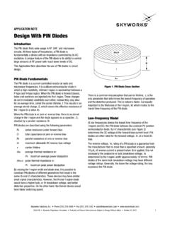
Transcription of APPLICATION NOTE …
1 APPLICATION NOTE. PIN Limiter Diodes in Receiver Protectors Introduction A Simple Limiter Circuit Radio and radar receivers must be capable of processing very A simple, passive receiver protection limiter is shown in Figure 2. small signals, necessitating the use of very sensitive circuit In its most fundamental form, this circuit consists of a PIN diode blocks that can contain fragile semiconductors. Many of these and an RF choke inductor, both of which are in shunt with the systems must also be capable of surviving very large incident main signal path.
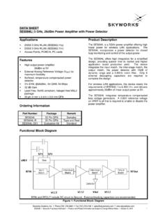
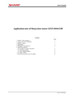
2 In most limiter circuits, DC blocking capacitors signals, without damage to the sensitive components they are included at the input and the output of the circuit. A single- contain. The receiver protection limiter, most often referred to stage limiter can typically reduce the amplitude of a large input simply as a limiter, can protect the receiver from large input signal by 20 30 dB. signals and also allow the receiver to function normally when DC DC. these large signals are not present. Block Block Limiters are most often employed in radar transceivers, whose Input Output transmitters and receivers are tuned to the same frequency.
3 The RF. Limiter transmitter produces a signal, the peak level of which is in most PIN Choke systems in the kilowatts or megawatts order of magnitude, which is applied to an antenna that is typically also utilized by the receiver. The receiver must be capable of reliably detecting and Figure 2. A Single-Stage Limiter processing very weak reflected signals, so it has a sensitive, low noise amplifier (LNA) at its input, although some receivers apply The PIN limiter diode can be described as an incident power- the received signal directly to the input of a downconverter mixer.
4 Controlled, variable resistor. In the case when no large input Both of these circuit blocks employ sensitive semiconductor signal is present, the impedance of the limiter diode is at its components that will very likely be damaged by even a small maximum, thereby producing minimum insertion loss, typically portion of the transmitter signal that might be coupled to the less than dB. The presence of a large input signal temporarily receiver input, either by reflection from the antenna or by other forces the impedance of the diode to a much lower value, means.
5 A limiter can protect these components. producing an impedance mismatch which reflects the majority Receiver Receiver Protecter Downconverter of the input signal power back towards its source. A nominal Limiter Mixer transfer curve for a limiter stage is shown in Figure 3. When the large input signal is no longer present, the impedance of the diode reverts from a very low value to its maximum value Low Noise Amplifier after a brief delay elapses. The limiter diode and its environment determine the duration of this delay. High Power Amplifier Transmitter Figure 1.
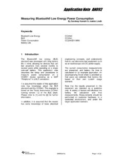
6 Simplified Radar Transceiver with a Receiver Protector Limiter Part of this paper was originally published EDN. Please refer to PIN-limiter diodes effectively protect receivers, EDN, December 17, 2004, 64. Skyworks Solutions, Inc. Phone [781] 376-3000 Fax [781] 376-3100 200480 Rev. C Skyworks Proprietary Information Products and Product Information are Subject to Change Without Notice. August 15, 2008 1. APPLICATION NOTE PIN LIMITER DIODES IN RECEIVER PROTECTORS. Limiter Output Pin-IL input signal clipped output signal 30 3.
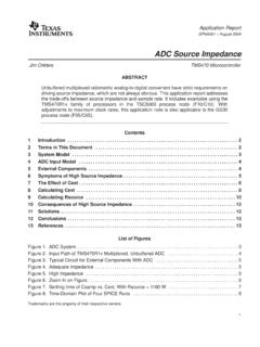
7 Low Insertion Limiting 2. 20 Loss Operation Operation Output Power (dBm). 1. Signal Voltage 1 dB 0. 10. -1. 0. Threshold Level -2. -10. -10 0 10 20 30 0 Input Power (dBm) Time Figure 3. Output Power vs. Input Power for a Single-Stage Limiter Input Output It is important to note that when a large input signal is present, Rectifying Rectifying the limiter diode reflects rather than dissipates the majority of Diode Diode the input signal power. In a properly designed circuit, a limiter diode that is capable of safely dissipating only a few hundred milliwatts is also capable of protecting a receiver from signals Figure 4.
8 Clipper Circuit and Large Signal many orders of magnitude larger, without damage to the limiter Input/Output Waveforms diode. Of course, this is based upon the assumption that the reflected signal is either re-radiated from the system antenna, or is directed by a non-reciprocal device, such as a circulator Clipper circuits are typically used for low frequency applications , or an isolator, to a resistive load that can dissipate the reflected nominally at VHF and below, since the stored charge of the recti- signal power. fier diodes limits rectification efficiency at higher frequencies.
9 This type of limiting circuit is often found in frequency modulation or phase modulation receiver IF amplifier sections. Clipper (Limiter) Circuit In the grey area where the frequency of a signal is at the Note that the PIN limiter circuit operates differently from another higher end of the range where clippers are useful, but at the class of limiter, known as a clipper, an example of which is lower end of the range where a PIN limiter circuit (as shown in shown in Figure 4. In that type of circuit, two rectifying diodes Figure 2) is utilized, an antiparallel pair of PIN diodes, such as (which could be Schottky or PN junction diodes) are utilized to SMP1330-005(1), can be used in the clipper circuit shown in limit the peak voltage of the positive and negative signal alterna- Figure 4.
10 In the lower UHF band, this circuit will act as a hybrid tions, either referenced to ground or to some arbitrarily selected of the clipper and the incident-power-controlled, variable DC level. This circuit, in this case with the rectifier diodes con- resistor limiter. nected to ground, allows signals whose amplitudes are less than the cut-in voltage of the rectifier diodes to pass unchanged. Signals whose voltage amplitudes are larger than the cut-in voltage of the rectifying junction will force the diode into conduction. In this case, the voltage drop across the diode is approximately V for a Si PN diode, so the peak voltage of the alternation that forward biases the diode is clamped to within a forward voltage drop of the potential to which the diode is connected.