Transcription of Unique Features of the MCP23X08/17 GPIO …
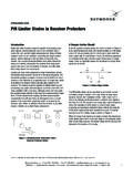
1 AN1043. Unique Features of the MCP23X08/17 gpio Expanders Author: Pat Richards I/O PORT DESCRIPTION. Microchip Technology Inc. The I/O port is highly configurable for maximum flexibility. Figure 1 is a simplified block diagram of an INTRODUCTION I/O port pin. The port can either drive logic levels on the pin, or read logic levels from the pad. The level on the gpio expanders provide easy I/O expansion using pad can be read at any time, regardless if the pin is standard serial interfaces. gpio products are used to configured as an input or an output. increase the I/O on an MCU or provide remote I/O. The IODIR register controls the direction of the pins using a serial interface. (input or output). More specifically, the IODIR registers This application note discusses the feature set and use simply enables/disables the output driver. When the of the MCP23X08/17 (8-bit and 16-bit) gpio Expand- driver is activated (IODIR = 0), the pad is driven to the ers. state in the latch register (OLAT).
2 When deactivated The mcp23x08 are 8-bit gpio Expanders: (IODIR = 1), the driver is high impedance. MCP23008: I2C Interface The I/O port has multiple, individual configurations. Each pin can . MCP23S08: SPI Interface The MCP23X17 are 16-bit gpio Expanders: be configured as an input. The output driver is disabled (high impedance). MCP23017: I2C Interface be configured as an output. The output driver MCP23S17: SPI Interface is enabled and the value in the latch is driven on The functions and Features of the mcp23x08 and the pin. MCP23X17 are basically the same, except where enable a weak pull-up resistor otherwise noted. emulate an open-drain configuration. This is accomplished by clearing the output latch (OLAT). Features bit to a zero and using the direction register (IODIR) to set the level on the pin. A pull-up This application note discusses some of the Features of resistor is required to pull the pin to voltage when the MCP23X08/17 and how they may be used in an the pin is an input application: - To drive a 0: configure the pin as an output I/O Port Description (IODIR = 0) so the port drives whatever is in 8/16-Bit Mode (MCP23X17 only) OLAT (logic 0 in this case).
3 Interrupt Features - To float a 1: set the pin as an input (IODIR = 1). The output driver is disabled - Mapping Interrupts and the pull-up resistor pulls the pin to a - Mirroring Interrupts (MCP23X17 only) logic 1. - Servicing Interrupts Internal Address Pointer Control Hardware Address Pin on SPI. 2006 Microchip Technology Inc. DS01043A-page 1. AN1043. FIGURE 1: I/O PORT BLOCK DIAGRAM TABLE 1: MEMORY MAP. VDD 8-bit Mode 16-bit Mode Register Address Register Address MCP23X08/17 Name (hex) Name (hex). IODIRA 00 IODIRA 00. Data Bus D. SET. Q. Write IPOLA 01 IODIRB 01. I/O. CLR Q Pad GPINTENA 02 IPOLA 02. OLAT or gpio DEFVALA 03 IPOLB 03. D. SET. Q Input Write Buffer INTCONA 04 GPINTENA 04. CLR Q IOCON 05 GPINTENB 05. IODIR. GPPUA 06 DEFVALA 06. Q. SET. D INTFA 07 DEFVALB 07. Q CLR. INTCAPA 08 INTCONA 08. Read GPIOA 09 INTCONB 09. Port OLATA 0A IOCON 0A. IODIRB 10 IOCON 0B. 8/16 BIT MODE (MCP23X17 ONLY) IPOLB 11 GPPUA 0C. The MCP23X17 has the Unique ability to appear to the GPINTENB 12 GPPUB 0D.
4 MCU as either two (2) 8-bit gpio expanders, or as a DEFVALB 13 INTFA 0E. single 16-bit gpio expander. INTCONB 14 INTFB 0F. This is accomplished by splitting the 16 I/O ports into IOCON 15 INTCAPA 10. two separate 8-bit I/O ports (Port A and Port B) via GPPUA 16 INTCAPB 11. INTFB 17 GPIOA 12. Each port has a group of dedicated registers. Table 1. shows how the register groups (Port A and Port B) are INTCAPB 18 GPIOB 13. mapped when in 8-bit or 16-bit mode. GPIOB 19 OLATA 14. OLATB 1A OLATB 15. Note: Unlike all other registers which are not shared between the two ports (Port A and Port B), there is one register (IOCON). which is shared between the ports and affects both equally. 8-Bit Mode: When in 8-bit mode, the ports' registers are separated: Port A register addresses range from 00h 0Ah Port B register addresses range from 10h 1Ah 16-bit Mode: When in 16-bit mode, the ports' registers are interleaved to emulate 16-bit wide registers: Port A and Port B register addresses range from 00h 15h.
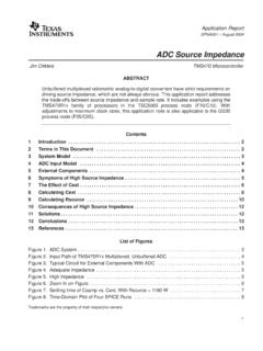
5 The registers are still addressed as 8-bit ports, meaning that the 16-bit mapping pair is always an even number ( , IODIR starts at 00h, IPOL starts at 02h, etc.). DS01043A-page 2 2006 Microchip Technology Inc. AN1043. INTERRUPT Features Interrupt Conditions The mcp23x08 has one interrupt pin and the There are several configurable interrupt conditions MCP23X17 has two interrupt pins. which allow flexible configurations. For the MCP23X17, each interrupt pin is associated INTERRUPT-ON-PIN-CHANGE. with an 8-bit port. INTA is associated with Port A and INTB is associated with Port B. Pins configured for interrupt-on-pin-change will cause an interrupt to occur if a pin changes to the Interrupt Mapping opposite state. The default state is reset after an interrupt is serviced. For example, an interrupt occurs The MCP23X17 interrupt pins can be mapped in two by an input changing from 1 to 0. The interrupt is then ways (see Figure 2) as controlled by : serviced while the pin state is still 0 by reading gpio or 1.
6 Interrupt pins operate independently. INTA INTCAP register. The new initial state for the pin is a reflects interrupt conditions on Port A and INTB logic 0. Likewise, if the pin is toggled back to a logic 1. reflects interrupt conditions on Port B. before servicing the interrupt, the new default state is a logic 1. 2. Both interrupt pins go active when an interrupt occurs on either port. The interrupt condition is cleared by reading either INTCAP or gpio register. The new pin state default is Interrupt Polarity and Open-Drain set when the interrupt is cleared. The interrupts can be configured to operate in three INTERRUPT-ON-CHANGE FROM DEFVAL. modes: REGISTER VALUE. 1. Active-High. Pins configured for interrupt-on-change from 2. Active-Low. register value will cause an interrupt to occur if the 3. Open-Drain. corresponding input pin differs from the register bit. The interrupt condition will remain as long as the condition The interrupt polarity and open-drain is configured via exists, regardless if the INTCAP or gpio is read.
7 INTPOL and ODR bits in the IOCON register. For example, if DEFVAL<b0> = 0. An interrupt will occur if the pin changes to a logic 1 and the interrupt Note: For the MCP23X17, the polarity and open- will remain as long as the pin remains a logic 1. The drain configuration of the INTA and INTB. interrupt condition will clear if the pin changes back to pins are not independent. Both pins are a logic 0 and INTCAP or gpio is read. configured the same. FIGURE 2: INTERRUPT BLOCK DIAGRAM. 0. 1. INTA. Open- A Polarity Drain Control B Control INTB. 0. 1. 2006 Microchip Technology Inc. DS01043A-page 3. AN1043. FIGURE 3: INTERRUPT-ON-PIN-CHANGE EXAMPLE. Change cause interrupt. Port state captured in INTCAP Change cause interrupt. No affect on INT pin or Port state captured in INTCAP INTCAP. GP3. Interrupt cleared and re-enabled INT. SPI. Read INTCAP or gpio Read INTCAP or gpio . Given: - GP3 configured to interrupt-on-pin-change . - INT pin configured for active low . FIGURE 4: INTERRUPT-ON-CHANGE-FROM-DEFVAL EXAMPLE.
8 GPINTEN gpio Interrupt-on-Change Enable Register GPINT7 GPINT6 GPINT5 GPINT4 GPINT3 GPINT2 GPINT1 GPINT0. X X X X 1 X X X. INTCON Interrupt Control Register IOC7 IOC6 IOC5 IOC4 IOC3 IOC2 IOC1 IOC0. X X X X 1 X X X. DEFVAL Default Value Register DEF7 DEF6 DEF5 DEF4 DEF3 DEF2 DEF1 DEF0. X X X X 0 X X X. Interrupt will occur if GP3 logic level = 1. Change cause interrupt. Port state captured in INTCAP. GP3 = DEF3. INT deactivates GP3 after SPI read INT remains because GP3 = 1. No affect on INT. (opposite of DEF3). pin or INTCAP. INT. SPI Read INTCAP or gpio . Read INTCAP or gpio . DS01043A-page 4 2006 Microchip Technology Inc. AN1043. INTERNAL ADDRESS POINTER For example, when configuring the device, it may be desirable to allow the address pointer to automatically CONTROL. increment so the device does not have to be re- Some slave serial devices automatically increment addressed after every byte. their internal address pointer after each byte is clocked Likewise, when performing a continuous operation on by the master.
9 This allows the master to sequentially a register ( , changing the outputs on a regular basis access multiple registers without re-sending the write by writing to gpio or OLAT), it may be beneficial to or read command. disable the address incrementing feature so that the Other slave devices do not automatically increment register is always accessed without re-addressing the their internal address pointer. register. The MCP23X08/17 family of devices have the ability to do either by configuring a control bit ( ). This allows maximum flexibility when accessing the registers. FIGURE 5: 8-BIT MODE: ADDRESS POINTER DISABLED (MCP23008 EXAMPLE). When the address pointer is DISABLED and the device is in 8-bit mode, the address pointer will not increment the address pointer. S 0 1 0 0 a a a 0 A 0 0 0 0 1 0 1 0 A 1 0 1 0 1 0 1 0 A 0 1 0 1 0 1 0 1 A 1 0 1 0 1 0 1 0 P. mcp23x08 Register Data @ Data @ Data Opcode Addr = 09h 09h 09h 09h GPIOA 09. OLATA 0A. IODIRB 10. IPOLB 11. GPINTENB 12. DEFVALB 13.
10 INTCONB 14. IOCON 15. GPPUB 16. INTFB 17. INTCAPB 18. See Figure 5 and Figure 6 for address pointer examples for the GPIOB 19 mcp23x08 8-bit devices and Figure 7 and Figure 8 for the OLATB 1A MCP23X17 examples. 2006 Microchip Technology Inc. DS01043A-page 5. AN1043. FIGURE 6: 8-BIT MODE: ADDRESS POINTER ENABLED (MCP23008 EXAMPLE). When the address pointer is ENABLED and the device is in 8-bit mode, the address pointer will increment after every byte is clocked. The address pointer will roll over to 00h after exceeding 1Ah (which is the last location of Port B). S 0 1 0 0 a a a 0 A 0 0 0 0 1 0 1 0 A 1 0 1 0 1 0 1 0 A 0 1 0 1 0 1 0 1 A 1 0 1 0 1 0 1 0 P. mcp23x08 Register Data @ Data @ Data Opcode Addr = 09h 09h 0Ah 10h GPIOA 09. OLATA 0A. IODIRB 10. IPOLB 11. GPINTENB 12. Note: The address pointer jumps DEFVALB 13 from 0Ah to 10h when transitioning INTCONB 14 from Port A to Port B. IOCON 15. GPPUB 16. INTFB 17. INTCAPB 18. GPIOB 19. OLATB 1A. FIGURE 7: 16-BIT MODE: ADDRESS POINTER DISABLED (MCP23017 EXAMPLE).