Transcription of Application note of Sharp dust sensor …
1 gp2y1010au0f . Application note of Sharp dust sensor gp2y1010au0f . Contents Page 1. Outline of this document 1. 2. Features of gp2y1010au0f 1. 3. Objects to detect 1. 4. Application 1. 5. Principle of dust detection 2. 6. Application guidance 6-1. Example of system connection 3. 6-2. Mounting method 4. 6-3. Basic output handling 5. 6-4. Other cautions 5. 7. dust density characteristics (Example) 6. Sheet No.: OP13024EN. Attachment-1. gp2y1010au0f . 1. Outline of this document This Application note of Sharp dust sensor gp2y1010au0f is a document consists from Explanation how to use, cautions when using it, characteristics data, etc.
2 For the customer's reference when applying this device. When designing the device, please refer to this document and also evaluate it under actual usage conditions. 2. Features of gp2y1010au0f . Compact thin package (46 30 ). With Application of pulse output system, the device can detect even single house dust . House dust and cigarette smoke can be distinguished. 3. Objects to detect House dust Cigarette smoke 4. Application Air conditioner Air purifier. Sheet No.: OP13024EN. Attachment-1. gp2y1010au0f . 5. Principles of dust detection This dust sensor gp2y1010au0f is the device to detect house dust , cigarette smoke, etc.
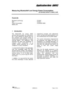
3 And designed as a sensor for automatic running of Application like air purifier and air conditioner with air purifier function. Light from the light emitter (Light Emitting Diode) is spotted with a lens and a slit as shown on the chart-A. Also for the light detector (Photodiode), a lens and a slit is positioned in front of it to cut disturbance light and to detect light reflection (when detecting dust ) efficiently. Area where those two optical axis cross is detection area of the device. Chart-B shows what is ongoing inside of the device when no dust exists and Chart-C shows that when dust exists.
4 The device makes voltage output even when dust is not being detected. This output voltage at no dust condition is specified as Voc on the specification. This is because light emitted from the LED reflects at case of the device some part of it gets to the detector. Chart-C shows how the device works when dust and/or cigarette smoke exists inside of it. In this case, the detector detects the light reflected from the dust and/or a particle of the cigarette smoke. Current in proportion to amount of the detected light comes out from the detector and the device makes analog voltage output (Pulse output) after the amplifier circuit amplifies the current from the detector.
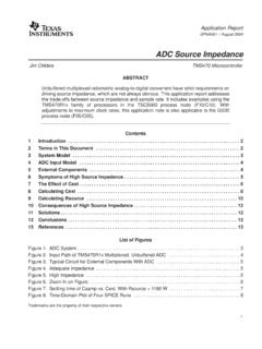
5 Sheet No.: OP13024EN. Attachment-2. gp2y1010au0f . 6. Application guidance 6-1 Example of system connection <Example>. +5V Vcc 66. R1=150 . V-LED. 1. Vcc +5V. C1=220 F Microcomputer LED. LED Driver 3. Output LED-GND. 2 +5V. Vo Detector AMP AMP AMP 5 A/D. dust . Input Cigarette smoke GND. S-GND. Sensitivity adjustment 44. Case Resister, R1=150 and capacitor, C1=220uF mentioned above is required for pulse drive of the LED of gp2y1010au0f . Please use the ones with the above mentioned constants. Without these cmponents, the device does not work.
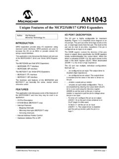
6 As input conditions of the LED terminal, please apply LED drive conditions mentioned in Electro-optical characteristics chart of the specification. When it is impossible to apply those conditions, please make it within the recommended input conditions mentioned in the specification. When the LED is driven under the condition beyond the specification, characteristics of the device will be affected. Specified Recommended Parameter Symbol Unit condition condition Pulse cycle T 10 10 1 ms Pulse width Pw ms The LED emits pulse light. Detected signal is amplified by the amplifier circuit and goes out as the output synchronized to the pulse mission of the LED.
7 The specified output value is the one that is measured after the LED is turned on. Therefore, it is recommended that microcomputer to read the output after the LED. emission also. Sampling timing of output pulse T=10ms ON. Light emission ILED OFF. Pw= Output pulse Sampling Time required for the device to be ready to detect dust from when the system is turned on is less than 1 sec. Sheet No.: OP13024EN. Attachment-3. gp2y1010au0f . 6-2 Mounting method There is a case that the sensor output may be affected when outer-light comes through dust through hole on the printed side.
8 In order to avoid any influence from outer-light, please locate the printed side of the sensor facing to inside of the Application . In order to avoid any influence from the attachment of dust to the inside of the sensor , please mount the sensor to the Application so that the outlet of the connector on the sensor turns to a downward direction. Please consider the structure and the mechanism of the equipment so that big dust (string dust , etc.) should not enter the inside of the sensor . The installation of a coarse mesh filter in front of dust through hole is effective for the capture of big dust .
9 Please consider the maintenance by vacuum cleaner in preparation for the false sensor output by the attachment of dust to the inside of the sensor . Sheet No.: OP13024EN. Attachment-4. gp2y1010au0f . 6-3 Basic output handling The output voltage Vo of this sensor is the sum of output voltage at no dust Voc and output proportional to dust density V. Output proportional to dust density V is shown as follows. V = Vo - Voc (Vo : monitor value). Output voltage at no dust Voc is caused by the stray light ocuurring in this sensor . This sensor makes Voc voltage even at dust density 0mg/m3.
10 If dust attached within this sensor increases, Voc becomes bigger. On the other hand, if dust attached within this sensor decreases, Voc becomes smaller. To store Voc in the memory of Application is necessary to calculate V from monitor value Vo. If monitor value Vo lower than the memorized Voc appears, this monitor value Vo should be stored in the memory of Application as a new Voc. If monitor value Vo maintains a bigger value than the memorized Voc for a certain period of time, this monitor value Vo should be stored in the memory of Application as a new Voc.