Transcription of Datasheet - L78L - Positive voltage regulators
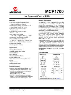
1 TO-92 SO-8 SOT-89 Features Output current up to 100 mA Output voltages of ; 5; 6; 8; 9; 10; 12; 15; 18; 24 V thermal overloadprotection Short-circuit protection No external components are required Available in either 4% (A) or 8% (C) selectionDescriptionThe L78L series of three-terminal Positive regulators employ internal current limitingand thermal shutdown, making them essentially indestructible. If adequate heat-sinkis provided, they can deliver up to 100 mA output current . They are intendedas fixed voltage regulators in a wide range of applications including local or on-card regulation for elimination of noise and distribution problems associated withsingle-point regulation. In addition, they can be used with power pass elements tomake high- current voltage regulators .
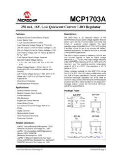
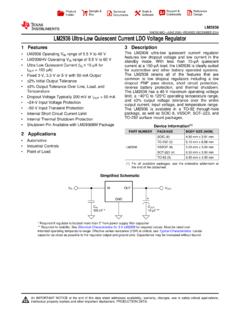
2 The L78L series used as Zener diode/resistorcombination replacement, offers e improvement along with lower quiescent currentand lower status linkL78 LPositive voltage regulatorsL78 LDatasheetDS0424 - Rev 28 - April 2021 For further information contact your local STMicroelectronics sales 1. Schematic diagramAMG160520161300 MTL78 LDiagramDS0424 - Rev 28page 2/402 Pin configurationFigure 2. Pin connection (top view, bottom view for TO-92)AMG160520161301 MTFigure 3. Test circuitsAMG160520161302 MTL78 LPin configurationDS0424 - Rev 28page 3/403 Maximum ratingsTable 1. Absolute maximum ratingsSymbolParameterValueUnitVIDC Input voltageVO = to 9 V30 VVO = 12 to 15 V35VO = 18 to 24 V40 IOOutput current100mAPDP ower dissipationInternally limited (1)mWTSTGS torage temperature range-65 to 150 CTOPO perating junction temperature rangefor L78 LxxAC / L78 LxxC0 to 125 Cfor L78 LxxAB-40 to 125 1.
3 Our SO-8 package used for voltage regulators is modified internally to have pins 2, 3, 6 and 7 electricallycommuned to the die attach flag. This particular frame decreases the total thermal resistance of thepackage and increases its ability to dissipate power when an appropriate area of copper on the printedcircuit board is available for heat-sinking. The external dimensions are the same as for the standard SO-8. Table 2. Thermal dataSymbolParameterSO-8TO-92 SOT-89 UnitRthJCThermal resistance junction-case (max)2015 C/WRthJAThermal resistance junction-ambient (max)55 (1)20055 (1) C/W 1. Considering 6 cm of copper Board heat-sink. L78 LMaximum ratingsDS0424 - Rev 28page 4/404 Electrical characteristicsTable 3. Electrical characteristics of L78L33C - Refer to the test circuits, TJ = 0 to 125 C, VI = V, IO = 40 mA, CI = F, CO = F unless otherwise specifiedSymbolParameterTest voltageTJ = 25 voltageIO = 1 to 40 mA, VI = to 20 = 1 to 70 mA, VI = VOLine regulationVI = to 20 V, TJ = 25 C150mVVI = to 20 V, TJ = 25 C100 VOLoad regulationIO = 1 to 100 mA, TJ = 25 C60mVIO = 1 to 40 mA, TJ = 25 C30 IdQuiescent currentTJ = 25 C6mATJ = 125 IdQuiescent current changeIO = 1 to 40 = to 20 noise voltageB = 10 Hz to 100 kHz, TJ = 25 C40 VSVRS upply voltage rejectionVI = to V, f = 120 HzIO = 40 mA, TJ = 25 C4149dBVdDropout voltage2 VTable 4.
4 Electrical characteristics of L78L05C - Refer to the test circuits, TJ = 0 to 125 C, VI = 10 V, IO = 40 mA, CI = F, CO = F unless otherwise specifiedSymbolParameterTest voltageTJ = 25 voltageIO = 1 to 40 mA, VI = 7 to 20 = 1 to 70 mA, VI = 10 VOLine regulationVI = to 20 V, TJ = 25 C200mVVI = 9 to 20 V, TJ = 25 C150 VOLoad regulationIO = 1 to 100 mA, TJ = 25 C60mVIO = 1 to 40 mA, TJ = 25 C30 IdQuiescent currentTJ = 25 C6mATJ = 125 IdQuiescent current changeIO = 1 to 40 = 8 to 20 noise voltageB = 10 Hz to 100 kHz, TJ = 25 C40 VSVRS upply voltage rejectionVI = 9 to 20 V, f = 120 HzIO = 40 mA, TJ = 25 C4049dBVdDropout voltage2VL78 LElectrical characteristicsDS0424 - Rev 28page 5/40 Table 5. Electrical characteristics of L78L08C - Refer to the test circuits, TJ = 0 to 125 C,VI = 14 V, IO = 40 mA, CI = F, CO = F unless otherwise specifiedSymbolParameterTest voltageTJ = 25 voltageIO = 1 to 40 mA, VI = to 20 = 1 to 70 mA, VI = 12 VOLine regulationVI = to 20 V, TJ = 25 C200mVVI = 11 to 20 V, TJ = 25 C150 VOLoad regulationIO = 1 to 100 mA, TJ = 25 C80mVIO = 1 to 40 mA, TJ = 25 C40 IdQuiescent currentTJ = 25 C6mATJ = 125 IdQuiescent current changeIO = 1 to 40 = 8 to 20 noise voltageB = 10 Hz to 100 kHz, TJ = 25 C60 VSVRS upply voltage rejectionVI = 9 to 20 V, f = 120 HzIO = 40 mA, TJ = 25 C3645dBVdDropout 6.
5 Electrical characteristics of L78L09C - Refer to the test circuits, TJ = 0 to 125 C, VI = 15 V, IO = 40 mA, CI = F, CO = F unless otherwise specifiedSymbolParameterTest voltageTJ = 25 voltageIO = 1 to 40 mA, VI = to 23 = 1 to 70 mA, VI = 15 VOLine regulationVI = to 23 V, TJ = 25 C250mVVI = 12 to 23 V, TJ = 25 C200 VOLoad regulationIO = 1 to 100 mA, TJ = 25 C80mVIO = 1 to 40 mA, TJ = 25 C40 IdQuiescent currentTJ = 25 C6mATJ = 125 IdQuiescent current changeIO = 1 to 40 = 12 to 23 noise voltageB = 10 Hz to 100 kHz, TJ = 25 C70 VSVRS upply voltage rejectionVI = 12 to 23 V, f = 120 HzIO = 40 mA, TJ = 25 C3644dBVdDropout characteristicsDS0424 - Rev 28page 6/40 Table 7. Electrical characteristics of L78L10C - Refer to the test circuits, TJ = 0 to 125 C, VI = 16 V, IO = 40 mA, CI = F, CO = F unless otherwise specifiedSymbolParameterTest voltageTJ = 25 voltageIO = 1 to 40 mA, VI = to 23 V911 VIO = 1 to 70 mA, VI = 16 V911 VOLine regulationVI = to 23 V, TJ = 25 C230mVVI = 13 to 23 V, TJ = 25 C170 VOLoad regulationIO = 1 to 100 mA, TJ = 25 C80mVIO = 1 to 40 mA, TJ = 25 C40 IdQuiescent currentTJ = 25 C6mATJ = 125 IdQuiescent current changeIO = 1 to 40 = 13 to 23 noise voltageB = 10 Hz to 100 kHz, TJ = 25 C60 VSVRS upply voltage rejectionVI = 14 to 23 V, f = 120 HzIO = 40 mA, TJ = 25 C3745dBVdDropout 8.
6 Electrical characteristics of L78L12C - Refer to the test circuits, TJ = 0 to 125 C, VI = 19 V, IO = 40 mA, CI = F, CO = F unless otherwise specifiedSymbolParameterTest voltageTJ = 25 voltageIO = 1 to 40 mA, VI = to 27 = 1 to 70 mA, VI = 19 VOLine regulationVI = to 27 V, TJ = 25 C250mVVI = 16 to 27 V, TJ = 25 C200 VOLoad regulationIO = 1 to 100 mA, TJ = 25 C100mVIO = 1 to 40 mA, TJ = 25 C50 IdQuiescent currentTJ = 25 = 125 C6mA IdQuiescent current changeIO = 1 to 40 = 16 to 27 noise voltageB = 10 Hz to 100 kHz, TJ = 25 C80 VSVRS upply voltage rejectionVI = 15 to 25 V, f = 120 HzIO = 40 mA, TJ = 25 C3642dBVdDropout characteristicsDS0424 - Rev 28page 7/40 Table 9. Electrical characteristics of L78L15C - Refer to the test circuits, TJ = 0 to 125 C, VI = 23 V, IO = 40 mA, CI = F, CO = F unless otherwise specifiedSymbolParameterTest voltageTJ = 25 voltageIO = 1 to 40 mA, VI = to 30 = 1 to 70 mA, VI = 23 VOLine regulationVI = to 30 V, TJ = 25 C300mVVI = 20 to 30 V, TJ = 25 C250 VOLoad regulationIO = 1 to 100 mA, TJ = 25 C150mVIO = 1 to 40 mA, TJ = 25 C75 IdQuiescent currentTJ = 25 = 125 C6mA IdQuiescent current changeIO = 1 to 40 = 20 to 30 noise voltageB = 10 Hz to 100 kHz, TJ = 25 C90 VSVRS upply voltage rejectionVI = to V, f = 120 HzIO = 40 mA, TJ = 25 C3339dBVdDropout 10.
7 Electrical characteristics of L78L18C - Refer to the test circuits, TJ = 0 to 125 C, VI = 27 V, IO = 40 mA, CI = F, CO = F unless otherwise specifiedSymbolParameterTest voltageTJ = 25 voltageIO = 1 to 40 mA, VI = 22 to 33 = 1 to 70 mA, VI = 27 VOLine regulationVI = 22 to 33 V, TJ = 25 C320mVVI = 22 to 33 V, TJ = 25 C270 VOLoad regulationIO = 1 to 100 mA, TJ = 25 C170mVIO = 1 to 40 mA, TJ = 25 C85 IdQuiescent currentTJ = 25 = 125 C6mA IdQuiescent current changeIO = 1 to 40 = 23 to 33 noise voltageB = 10 Hz to 100 kHz, TJ = 25 C120 VSVRS upply voltage rejectionVI = 23 to 33 V, f = 120 HzIO = 40 mA, TJ = 25 C3238dBVdDropout characteristicsDS0424 - Rev 28page 8/40 Table 11. Electrical characteristics of L78L24C - Refer to the test circuits, TJ = 0 to 125 C, VI = 33 V, IO = 40 mA, CI = F, CO = F unless otherwise specifiedSymbolParameterTest voltageTJ = 25 voltageIO = 1 to 40 mA, VI = 27 to 38 = 1 to 70 mA, VI = 33 VOLine regulationVI = 27 to 38 V, TJ = 25 C350mVVI = 28 to 38 V, TJ = 25 C300 VOLoad regulationIO = 1 to 100 mA, TJ = 25 C200mVIO = 1 to 40 mA, TJ = 25 C100 IdQuiescent currentTJ = 25 = 125 C6mA IdQuiescent current changeIO = 1 to 40 = 28 to 38 noise voltageB = 10 Hz to 100 kHz, TJ = 25 C200 VSVRS upply voltage rejectionVI = 29 to 35 V, f = 120 HzIO = 40 mA, TJ = 25 C3037dBVdDropout 12.
8 Electrical characteristics of L78L33AB and L78L33AC - Refer to the test circuits, TJ = 0 to 125 C (AC) TJ = -40to 125 C (AB),VI = V, IO = 40mA, CI = F, CO = F unless otherwise specifiedSymbolParameterTest voltageTJ = 25 voltageIO = 1 to 40 mA, VI = to 20 = 1 to 70 mA, VI = VOLine regulationVI = to 20 V, TJ = 25 C150mVVI = to 20 V, TJ = 25 C100 VOLoad regulationIO = 1 to 100 mA, TJ = 25 C60mVIO = 1 to 40 mA, TJ = 25 C30 IdQuiescent currentTJ = 25 C6mATJ = 125 IdQuiescent current changeIO = 1 to 40 = to 20 noise voltageB = 10 Hz to 100 kHz, TJ = 25 C40 VSVRS upply voltage rejectionVI = to V, f = 120 HzIO = 40 mA, TJ = 25 C4149dBVdDropout voltage2VL78 LElectrical characteristicsDS0424 - Rev 28page 9/40 Table 13.
9 Electrical characteristics of L78L05AB and L78L05AC - Refer to the test circuits, TJ = 0 to 125 C (AC) TJ = -40to 125 C (AB), VI = 10 V, IO = 40 mA, CI = F, CO = F unless otherwise specifiedSymbolParameterTest voltageTJ = 25 voltageIO = 1 to 40 mA, VI = 7 to 20 = 1 to 70 mA, VI = 10 VOLine regulationVI = to 20 V, TJ = 25 C150mVVI = 8 to 20 V, TJ = 25 C100 VOLoad regulationIO = 1 to 100 mA, TJ = 25 C60mVIO = 1 to 40 mA, TJ = 25 C30 IdQuiescent currentTJ = 25 C6mATJ = 125 IdQuiescent current changeIO = 1 to 40 = 8 to 20 noise voltageB = 10 Hz to 100 kHz, TJ = 25 C40 VSVRS upply voltage rejectionVI = 8 to 18 V, f = 120 HzIO = 40 mA, TJ = 25 C4149dBVdDropout voltage2 VTable 14. Electrical characteristics of L78L06AB and L78L06AC - Refer to the test circuits, TJ = 0 to 125 C (AC) TJ = -40to 125 C (AB)
10 , VI = 12 V, IO = 40 mA, CI = F, CO = F unless otherwise specifiedSymbolParameterTest voltageTJ = 25 voltageIO = 1 to 40 mA, VI = to 20 = 1 to 70 mA, VI = 12 VOLine regulationVI = to 20 V, TJ = 25 C150mVVI = 9 to 20 V, TJ = 25 C100 VOLoad regulationIO = 1 to 100 mA, TJ = 25 C60mVIO = 1 to 40 mA, TJ = 25 C30 IdQuiescent currentTJ = 25 C6mATJ = 125 IdQuiescent current changeIO = 1 to 40 = 9 to 20 noise voltageB = 10 Hz to 100 kHz, TJ = 25 C50 VSVRS upply voltage rejectionVI = 9 to 20 V, f = 120 HzIO = 40 mA, TJ = 25 C3946dBVdDropout characteristicsDS0424 - Rev 28page 10/40 Table 15. Electrical characteristics of L78L08AB and L78L08AC - Refer to the test circuits, TJ = 0 to 125 C (AC) TJ = -40to 125 C (AB), VI = 14 V, IO = 40 mA, CI = F, CO = F unless otherwise specifiedSymbolParam