Transcription of LTC3824 – High Voltage Step-Down Controller With 40µA ...
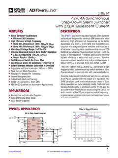
1 LTC382413824fhFor more information applicaTionFeaTuresapplicaTionsDescripTi onHigh Voltage Step-Down Controller With 40 A quiescent CurrentThe LT C 3824 is a Step-Down DC/DC Controller designed to drive an external P-channel MOSFET. With a wide input range of 4V to 60V and a high Voltage gate driver, the LTC3824 is suitable for many industrial and automotive high power applications. Constant frequency current mode operation provides excellent LTC3824 can be configured for Burst Mode operation. Burst Mode operation enhances low current efficiency (only 40 A quiescent current ) and extends battery run time. The switching frequency can be programmed up to 600kHz and is easily features include current limit, soft-start, micropower shutdown, and Burst Mode LTC3824 is available in a 10-lead MSE power Buck Convertern Wide Input Range: 4V to 60Vn current Mode Constant Frequency PWMn Very Low Dropout Operation: 100% Duty Cyclen Programmable Switching Frequency: 200kHz to 600kHzn Selectable High Efficient Burst Mode Operation.
2 40 A quiescent Currentn Easy Synchronizationn 8V, 2A Gate Drive (VCC > 10V) for Industrial High Voltage P-Channel MOSFETn Programmable Soft-Startn Programmable current Limitn Available in a Small 10-Pin Thermally Enhanced MSE Packagen Industrial and Automotive Power Suppliesn Telecom Power Suppliesn Distributed Power SystemsL, LT, LTC, LTM and Burst Mode are registered trademarks of Linear Technology Corporation. All other trademarks are the property of their respective owners. Protected by Patents including and Power Loss vs Load current 3824 51 F422k100pFCOUT100 F 222 F392kCIN33 TO 60V+LOAD current (mA)6070 EFFICIENCY (%)POWER LOSS (W)9080101003824 LOSS20001000 VIN = 12 VVIN = 40 VVIN = 40 VVIN = 12 VLTC382423824fhFor more information conFiguraTionabsoluTe MaxiMuM raTingsVCC ..65 VSS, RSET, VFB.
3 4 VVC ..3 VSYNC/MODE ..6 VVCC VSENSE ..1 VOperating Junction Temperature Range (Note 2) .. 55 C to 150 CStorage Temperature Range .. 65 to 150 CLead Temperature (Soldering, 10 sec) ..300 C(Note 1)12345 GNDSYNC/MODERSETVCVFB10987611 GNDCAPGATEVCCSENSESSTOP VIEWMSE PACKAGE10-LEAD PLASTIC MSOP TJMAX = 150 C, JA = 43 C/W, JC = 3 C/W EXPOSED PAD (PIN 11) IS GND, MUST BE SOLDERED TO PCBorDer inForMaTionLEAD FREE FINISHTAPE AND REELPART MARKING*PACKAGE DESCRIPTIONTEMPERATURE RANGELTC3824 EMSE#PBFLTC3824 EMSE#TRPBFLTBRZ10-Lead Plastic MSOP 40 C to 125 CLTC3824 IMSE#PBFLTC3824 IMSE#TRPBFLTCGZ10-Lead Plastic MSOP 40 C to 125 CLTC3824 HMSE#PBFLTC3824 HMSE#TRPBFLTCGZ10-Lead Plastic MSOP 40 C to 150 CLTC3824 MPMSE#PBFLTC3824 MPMSE#TRPBFLTCGZ10-Lead Plastic MSOP 55 C to 150 CLEAD BASED FINISHTAPE AND REELPART MARKING*PACKAGE DESCRIPTIONTEMPERATURE RANGELTC3824 EMSELTC3824 EMSE#TRLTBRZ10-Lead Plastic MSOP 40 C to 125 CLTC3824 IMSELTC3824 IMSE#TRLTCGZ10-Lead Plastic MSOP 40 C to 125 CLTC3824 HMSELTC3824 HMSE#TRLTCGZ10-Lead Plastic MSOP 40 C to 150 CLTC3824 MPMSELTC3824 MPMSE#TRLTCGZ10-Lead Plastic MSOP 55 C to 150 CConsult LTC Marketing for parts specified with wider operating
4 Temperature ranges. *The temperature grade is identified by a label on the shipping more information on lead free part marking, go to: For more information on tape and reel specifications, go to: Some packages are available in 500 unit reels through designated sales channels with #TRMPBF more information characTerisTics The l denotes the specifications which apply over the specified operating junction temperature range, otherwise specifications are at TA = 25 C (Note 2). VCC = 12V, RSET = 392k, CCAP = F. No load on any outputs, unless otherwise Voltage (VCC)l460 VSupply current (IVCC)VC (Switching Off), VCC 60V VSYNC = 0V (Burst Mode Operation Disable) current (IVCC) Burst Mode OperationVCC 60V, SYNC/MODE Open, VC = ASupply current in ShutdownVC 25mV, VCC 60V l920 30 A AVC 25mV, VCC = 12V l510 15 A AVoltage Amplifier gmReference Voltage (VREF) LTC3824E/LTC3824I LTC3824MP/LTC3824H l V VTransconductanceVC = , IVC = 2 A220260370 mhoFB Input CurrentVFB = VREF (Note 3).
5 LTC3824E/LTC3824I LTC3824MP/LTC3824Hl l10 1030 60nA nAVC HighIVC = LowIVC = Source CurrentVVC = to , VFB = VREF 100mV (VSYNC = 0V)15 AVC Sink CurrentVVC = to , VFB = VREF +100mV (VSYNC = 0V)15 AVC Threshold for Switching OffVSYNC/MODE = 0V (Note 4) current ISSVSS = to l3 8 A AVC Burst Mode ThresholdVCC 60V, VC Rising, SYNC/MODE Burst Mode Threshold HysteresisVCC Voltage at Burst Mode Operation(VCC VSENSE) at 30% Duty Cycle 70% Duty Cycle30 20mV mVCurrent Limit Threshold (VCC VSENSE)VCC 60V: LTC3824E/LTC3824I LTC3824MP/LTC3824Hl l80 75100 100120 120mV mVFB Overvoltage ThresholdVC = Input CurrentVSENSE = AOscillatorSwitching FrequencyRSET = 392k: LTC3824E/LTC3824I LTC3824MP/LTC3824Hl l170 170200 200230 240kHz kHzRSET = 200kl320400460kHzSynchronization Pulse Threshold on SYNC PinRising Edge Frequency RangeRSET = 392k RSET = 200kl l230 460300 600kHz kHzVRSETRSET = On-Time (Measured at GATE Pin)CCM Operation (Note 5)350nsSwitching Frequency FoldbackVFB = more information characTerisTicsNote 1: Stresses beyond those listed under Absolute Maximum Ratings may cause permanent damage to the device.
6 Exposure to any Absolute Maximum Rating condition for extended periods may affect device reliability and 2: The LTC3824 is tested under pulsed load conditions such that TJ TA. The LTC3824E is guaranteed to meet performance specifications from 0 C to 85 C operating junction temperature. Specifications over the 40 C to 125 C operating junction temperature range are assured by design characterization and correlation with statistical process controls. The LTC3824I is guaranteed over the 40 C to 125 C operating junction temperature range. The LTC3824H is guaranteed over the 40 C to 150 C operating junction temperature range. The LTC3824MP is guaranteed and tested over the full 55 C to 150 C operating junction temperature range. High junction temperatures degrade operating lifetimes; operating lifetime is derated for junction temperatures greater than 125 C.
7 Note that the maximum ambient temperature consistent with these specifications is determined by specific operating conditions in conjunction with board The l denotes the specifications which apply over the specified operating junction temperature range, otherwise specifications are at TA = 25 C (Note 2). VCC = 12V, RSET = 392k, CCAP = F. No load on any outputs, unless otherwise DriverGATE Bias Voltage (VCC VCAP)9V VCC 60V, IGATE = 10mA: LTC3824E/LTC3824I LTC3824MP/LTC3824Hl VVCC = 12V, IGATE = Bias Voltage (VCAP GND)4V VCC 8V, IGATE = 10mA 6V VCC 8V, IGATE = 15mA VGATE High Voltage (VCC VGATE)4V VCC 60V, IGATE = Peak Source CurrentCGATE = Low Voltage (VGATE VCAP)8V VCC 60V, IGATE = 15mA 4V VCC < 8V, IGATE = VGATE Peak Sink CurrentCGATE = , the rated package thermal impedance and other environmental factors.
8 The junction temperature (TJ, in C) is calculated from the ambient temperature (TA, in C) and power dissipation (PD, in Watts) according to the formula: TJ = TA + (PD JA)where JA (in C/W) is the package junction to ambient thermal 3: This parameter is tested in a feedback loop that servos VFB to the reference Voltage with the VC pin forced to 4: This specification represents the maximum Voltage on VC where switching (GATE pin) is guaranteed to be off. The nominal value of VC where switching turns off is 5: The LTC3824 typically enters Burst Mode operation when the load is less than one third the current limit. If minimum on-time is violated, cycle skipping may occur at higher current more information perForMance characTerisTics (VCC VCAP) vs IGATE at VDRIVE Low ICC vs VCCS witching Frequency Change vs VCC at RSET = 392k VREF Change vs VCC Switching Frequency vs RSET VREF vs TemperatureTA = 25 C unless otherwise (mA)010 VCC-VCAP (V) (V)00 ICC (mA)123102030403824 G025060 VFB = = (V)0 3 FREQUENCY (kHz) 2 1013102030403824 G0350602 VCC (V)0 VREF (mV) G045060 DIE TEMPERATURE ( C) 75 50 2 VREF (mV) 1015432 25025503824 G0675 100150125 RSET(k )100100 FREQUENCY (kHz)
9 2003004005007002003003824 G05400600 LTC382463824fhFor more information Mode Disabled atILOAD = 200mA, VOUT = 5V Burst Mode Operation VOUT = 3V Burst Mode Operation VOUT = 5 VTypical perForMance characTerisTics Load current Step ResponseVOUT10mV/DIVINDUCTORCURRENT1A/DI V4 s/DIV3824 G07 ILOAD = 200mAVOUT50mV/DIVINDUCTORCURRENT1A/DIV20 s/DIV3824 G08 VIN =12V, VOUT= 3V, ILOAD = 200mAVOUT50mV/DIVINDUCTORCURRENT1A/DIV50 s/DIV3824 G09 VIN =12V, VOUT= 5V, ILOAD = 200mAOUTPUT VOLTAGEAC COUPLED100mV/DIVINDUCTORCURRENT2A/DIV100 s/DIV3824 G10TA = 25 C unless otherwise more information FuncTionsGND (Pin 1, Exposed Pad Pin 11): Ground. Exposed pad must be soldered to PCB with expanded metal trace for rated thermal (Pin 2): Synchronization Input and Burst Mode Operation Enable/Disable. If this pin is left open or pulled higher than 2V, Burst Mode operation will be enabled at light load and the typical threshold of entering Burst Mode operation is one third of current limit.
10 If this pin is grounded or the synchronization pulse is present with a frequency greater than 20kHz then Burst Mode operation is disabled and the LTC3824 goes into pulse skipping at light loads. To synchronize the LTC3824 , the duty cycle of the synchronizing pulse can range from 10% to 70% and the synchronizing frequency has to be higher than the programmed frequency. RSET (Pin 3): A resistor from RSET to ground sets the LTC3824 switching frequency. VC (Pin 4): The Output of the Voltage error amplifier gm and the control signal of the current mode PWM control loop. Switching starts at , and higher VC corresponds to higher inductor current . When VC is pulled below 25mV, the LTC3824 goes into micropower (Pin 5): Error Amplifier Inverting Input. A resistor divider to this pin sets the output Voltage .


