Transcription of Dimming Techniques for Switched-Mode LED Drivers
1 LM3406,LM3409 Dimming Techniques for Switched-Mode LED DriversLiterature Number: SNVA605 POWER designer Expert tips, tricks, and Techniques for powerful designs No. 119 No. 126 Dimming Techniques for Switched-Mode LED Drivers By Rich Rosen, Field Applications Engineer Feature Article .. 1-6 TRIAC Dimmable LED Driver ..2 IntroductionTh e exponential growth of LED lighting has ushered in a vast selection of integrated circuit devices to provide controlled power to LEDs. No longer acceptable to an energy-conscious world, Switched-Mode LED Drivers have long since replaced power-hungry linear current sources as the standard. Applications from fl ashlights to stadium scoreboards all require precise control of regulated currents. In many instances, real-time changes in LED output intensity are required.
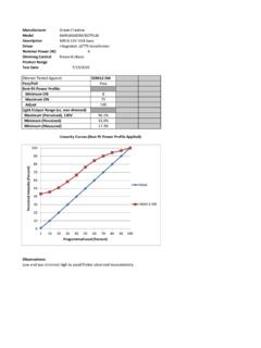
2 Th is function is commonly referred to as Dimming control. Th is article describes some basic LED theory and several Techniques used to provide Dimming control to Switched-Mode LED Brightness and Color TemperatureLED BrightnessTh e concept of the brightness of visible light from an LED is fairly easy to understand. Assigning a numerical value to the perceived brightness of an LED s output can simply be measured in units of luminous fl ux density, called candelas (cd). Th e total power output of an LED is a measurement of the amount of Lumens (lm).It is also important to under-stand that average forward LED current determines the brightness of an LED. Figure 1 shows the relation-ship between forward LED current vs. Lumens output for a certain LED.
3 Th e rela-tionship is remarkably linear over useable ranges of IF or forward current. Note the nonlinearity appearing as IF increases. Reduced effi cacy in Lumens per Watt arises as the operating current exceeds the linear range. POWER designer Expert tips, tricks, and Techniques for powerful designsLED Current (IF)0 mA1A500 mA05001000 Lumens OutputIdeal linearlm vs. ILED Characteristicfrom datasheetPd as heatFigure 1. LED Output vs. LED Dimming Performance. High Effi Performance, TRIAC Dimmable LED Driver National s industry-leading TRIAC dimmable offl ine LED driver solution is perfect for any application where an LED driver must interface to a standard TRIAC wall dimmer. National s new TRIAC dimmable LED driver delivers a wide, uniform Dimming range free of fl icker, best-in-class Dimming performance, and high effi ciency all while maintaining ENERGY STAR power factor requirements in a typical application.
4 2009, National Semiconductor Corporation. National Semiconductor, , WEBENCH, and PowerWise are registered trademarks. All rights Range Dimming CapabilityNational s TRIAC dimmable LED driver offers 100:1 full range Dimming capability, going from full light to nearly imperceptible light in a continuous range without being extinguished, and maintains a constant current to large strings of LEDs driven in series off of a standard line voltage. Uniform Dimming Without FlickerNational s TRIAC dimmable LED driver allows master-slave operation control in multi-chip solutions which enables a single TRIAC dimmer to control multiple strings of LEDs with smooth consistent Dimming , free of fl icker. Easy To UseNational s TRIAC dimmable LED driver enables a direct replacement of incandescent or halogen lamp systems that are currently interfaced to a TRIAC dimmer without having to change the original infrastructure or sacrifi ce performance.
5 In addition, the new TRIAC dimmable LED driver is available in WEBENCH LED Designer to allow for easy and quick design Dimmable LED Driver TRIAC Wall Dimmer VAC3 designerDimming Techniques for Switched-Mode LED Drivers Operation above the linear range results in output power converted to heat from the LED. Th is wasted heat burdens the LED driver and increases the complexity of the thermal Color TemperatureColor temperature is a metric that describes the color of the LED and is quantifi ed in LED datasheets. Th e color temperature of a given LED will be specifi ed within a range and will shift with variances in forward current, junction temperature, and age. Lower color temperatures are more red-yellow (called warm) and higher-valued color temperatures are more blue-green (called cooler).
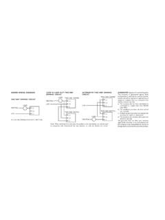
6 Many colored LEDs will specify dominant wavelength instead of color temperature and are also subject to shift in Dimming MethodsTwo popular methods for Dimming LEDs in Switched-Mode driver circuits exist: Pulse-Width Modulation (PWM) Dimming and analog Dimming . Both methods control the time-averaged current through the LED or LED string, but there are diff erences between the two which become evident when examining the advantages and disadvantages of the two types of Dimming 2 shows a Switched-Mode LED driver in a buck topology. VIN must always be higher than the voltage across the LED + RSNS. Th e inductor current is the LED current. Th e current is regulated by monitoring the voltage at the current sense or CS pin.
7 As current sense or CS starts to fall below a set voltage, the duty cycle of the current pulses going through L1, the LED and RSNS increase; which increases the average LED current. Analog DimmingAnalog Dimming of LEDs is the adjustment of cycle-by-cycle LED current. More simply put, it is the adjustment of the constant LED current Dimming can be accomplished by an adjustment of the current sense resistor RSNS, or by driving an analog voltage on some DIM function pin of the IC. Figure 2 shows two examples of analog Dimming . Analog Dimming by Adjustment of RSNSIt is clear from Figure 2 that a change in value of RSNS will correspond to a change in LED current with a fi xed CS reference voltage. If one could fi nd a potentiometer that could handle the high LED current and also was available in sub-1 Ohm values, this would be a viable method to dim the ,VINSD1L1 CBRSNSCFRONCINVINIFVCCCSCOMPCCF igure 2.
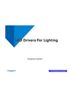
8 Buck Regulator Topology4 POWER designerDimming Techniques for Switched-Mode LED DriversTh e Dimming of the LED now becomes propor-tional to the duty cycle of the Dimming waveform, governed by the formula: IDIM-LED = DDIM x ILED where IDIM-LED is the average LED current, DDIM is the duty cycle of the dim waveform, and ILED is the nominal LED current setup with the selection of RSNS as shown in Figure the LED DriverMany modern LED Drivers feature a specialized PWM DIM pin that accepts a wide range of PWM frequencies and amplitudes, allowing a simple interface to external logic. Th e DIM function only shuts down the output drive while leaving the internal circuitry operating, avoiding the delay of restarting the IC. Output Enable pins and other logic shutdown functions can be PWM DimmingTwo-wire PWM Dimming is a popular method for automotive interior lighting.
9 As VIN is modulated below 70% of VIN-NOMINAL, the VINS pin (Figure 3) detects the change in voltage and converts the PWM waveform into a corresponding PWM of the output drive. Th e disadvantage to this method is the power source to the converter must contain a circuit to provide a PWM waveform to its DC Dimming by Driving DC Voltage on the CS PinMore complex is a technique to directly control the cycle-by-cycle current of the LED by means of driving a voltage into the CS pin. Th e voltage source is typically inserted into a feedback loop where LED current is sampled and buff ered by the amplifi er (Figure 2). Th e LED current can be controlled by the gain of the amplifi er. With this feedback circuitry, functionality such as current and thermal foldback can be implemented for further LED disadvantage to analog Dimming is that the color temperature of the emitted light can vary as a function of LED current.
10 In situations where the color of the LEDs is critical, or the particular LED exhibits a large change in color temperature with changes in LED current, Dimming the output of the LED by changing the LED current would be DimmingTh e PWM method of Dimming is the actual start and restart of the LED current for short periods of time. Th e frequency of this start-restart cycle must be faster than the human eye can detect to avoid a fl ickering eff ect, about 200 Hz or faster is usually 3. Two-Wire PWM Dimming5 designerDimming Techniques for Switched-Mode LED Drivers Fast PWM Dimming with a Shunt DeviceBecause of the delays in shutdown and start up of the converter s output, there is a limit to the PWM Dimming frequency and range of duty cycles.