Transcription of Eddy Current Losses in Transformer Windings and Circuit …
1 Eddy Current Losses in Transformer Windings and Circuit Wiring Lloyd H. Dixon, Jr. Introduction energy is stored in air gaps, insulation between As switching power supply operating fre- conductors, and within the conductors, where quencies increase, eddy Current Losses and relative permeability JLr is essentially and parasitic inductances can greatly impair Circuit constant. The energy density then becomes: performance. These high frequency effects are w = \BH = \'tJ.(j/I2 J/m3. caused by the magnetic field resulting from Current flow in Transformer Windings and Circuit where ILOis the absolute permeability of free space ( =47r .10"7 in units). Total energy W. wiring. This paper is intended to provide insight into (Joules) is obtained by integrating the energy these phenomena so that improved high fre- density over the entire volume, v, of the field: quency.)
2 Performance can be achieved. Among W = \ILO f H2dv Joules other things, it explains (I) why eddy Current Losses increase so dramatically with more wind- Within typical transformers and inductors, the ing layers, (2) why parallelling thin strips does- magnetic energy is almost always confined to n't work, (3) how passive conductors (Faraday regions where the field intensity H is relatively shields and . Windings ) have high Losses , constant and quite predictable. This often oc- and (4) why increasing conductor surface area curs in Circuit wiring, as well. In these cases: will actually worsen Losses and parasitic induc- W = \ILO H2A. e Joules (2). tance if the configuration is not correct.
3 And from (1), He = NI. Substituting for H: Basic Principles W = \ILO ~fA/e Joules (3). The following principles are used in the development of this topic and are presented whereA is the cross-section area (m1 of the here as a review of basic magnetics. region normal to the flux, and e is the length 1. Ampere's Law: The total magneto-motive of the region in meters (and the effective force along any closed path is equal to the total length of the field). Current enclosed by that path: 4. Circuit inductance: Inductance is a meas- ure of an electrical Circuit 's ability to store F = iHde = I, = NI Amps (1). magnetic energy . Equating the energy stored in where F is the total magneto-motive force the field from (3) with the same energy in (in Amperes) along a path of length e (m), H Circuit terms: is field intensity (Aim), and I, is the total W = \Lf = \ILO N2fA/e Current through all turns enclosed by the path.)
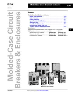
4 2. Conservation or energy : At any moment L = ILON2A/e (4). of time, the Current within the conductors and Skin Effect the magnetic field are distributed so as to Figure 1 shows the magnetic field (flux lines). minimize the energy taken from the source. in and around a conductor carrying dc or low 3. energy content or the field: The magnetic frequency Current I. The field is radially sym- field is energy . The energy density at any point metrical, as shown, only if the return Current in the field is: with its associated field is at a great distance. w = f HdB Jouleslm3 At low frequency, the energy in the magnetic field is trivial compared to the energy loss in where B is the flux density (Tesla).
5 In the resistance of the wire. Hence the Current switching power supplies, almost all magnetic R2-1. reduced, so the resistance at high frequency ( and resulting Losses ) can be many times gJ:eater than at low freQuencv. Fig. 1 -IsQ/ated CQnductQr at LQW Frequency distributes itself uniformly throughout the wire so as to minimize the resistance loss and the total energy expended. Fig. 3 -High Frequency Cu"ent Distribution Around any closed path outside the wire Penetration depth: Penetration or skin (and inside the return Current ), magneto-motive depth, OPEN, is defmed as the distance from force F is constant and equal to total Current I. the surface to where the Current density is l/e But field intensity H varies inversely with the times the surface Current density ( e is the r,adial distance, because constant F is applied naturallog base)[l]: across an increasing t ( =2m).
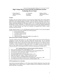
6 OPEN = [ p/(1 TIJ. )]112 m (5). Within the conductor, F at any radius must equal the enclosed Current at that radius, where p is resistivity. For copper at 100 C, therefore F is proportional to r2. p = n-cm, = 7,and: OPEN = ( )112 cm (6). From (6), OPEN= .024 cm at 100 kHz, or .0075 cm at 1 MHz. Eqs. (5) and (6) are accurate for a flat con- ductor surface, or when the radius of curvature is much greater than the penetration depth. Although the Current density tails off expo- Fig. 2 -Eddy Current at High Frequency nentially from the surface, the high frequency At high frequency: Figure 2 is a super- resistance (and loss) is the same as if the cur- position model that explains what happens rent density were constant from the surface to when the frequency rises.
7 The dash lines repre- the penetration depth, then went abruptly to sent the uniform low frequency Current distri- zero as shown on the right hand side of Fig. 3. bution, as seen in Fig. I. When this Current This equivalent rectangular distribution is changes rapidly, as it will at high frequency, the easier to apply. flux within the wire must also change rapidly. Equivalent Circuit model: Another way of The changing flux induces a voltage loop, or looking at the high frequency effects in trans- eddy, as shown by the solid lines near the wire former Windings and Circuit wiring is through surface. Since this induced voltage is within a the use of an equivalent electrical Circuit conductor, it causes an eddy Current coincident model.
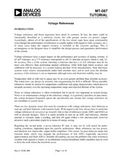
8 This approach is probably easier for a with the voltage. Note how this eddy Current Circuit designer to relate to. reinforces the main Current flow at the surface, Figure 4 is the equivalent Circuit of the but opposes it toward the center of the wire. isolated conductor of Figs. 1 to 3. With Current The result is that as frequency rises, Current I flowin, through the wire, L% accounts for the density increases at the conductor surface and energy ~L%I2 stored in the external magnetic decreases toward zero at the center. as shown field. L% is the inductance of the wire at high in Fig. 3. The Current tails off exponentially frequencies. within the conductor. The portion of the Point A represents the outer surface of the conductor that is actually carrying Current is conductor, while B is at the center.
9 R; is the R2-2. lowering the total resistance and reducing the energy going into Losses . Finally, conduction is uniform throughout the wire, no further energy goes into the magnetic fields external or internal to the wire, and a small amount of energy continues to be dissipated in Ri over time. Note that the concept of skin depth has no Fig. 4 -Conductor Equivalent Circuit meaning in the time domain. resistance, distributed through the wire from The frequency domain: Referring again to surface to center. Think of the wire as divided Fig. 4 with a sine wave Current applied to the into many concentric cylinders of equal cross terminals, it is apparent that at low frequencies, section area.
10 The Ri elements shown in the the reactance of internal inductance Li is neg- drawing would correspond to the equal resis- ligible compared to Ri. Current flow is uniform tance of each of the cylinders. Likewise, the throughout the wire and resistance is minimum. internal inductance L; accounts for the magnet- But at high frequency, Current flow will be ic energy distributed through the cylindrical greatest at the surface (A), tailing off exponen- sections. The energy stored in each section tially toward the center (B). depends on the cumulative Current flowing Penetration depth (skin depth) is clearly through the elements to the right of that relevant in the frequency domain. At any section in the equivalent Circuit .