Transcription of EPC2019 – Enhancement Mode Power Transistor
1 EGaN FET DATASHEET EPC2019 . EPC2019 Enhancement Mode Power Transistor VDS, 200 V D. RDS(on) , 42 mW max G EFFICIENT Power CONVERSION. ID , A HAL. S. Gallium Nitride's exceptionally high electron mobility and low temperature coefficient allows very low RDS(on), while its lateral device structure and majority carrier diode provide exceptionally low QG. and zero QRR. The end result is a device that can handle tasks where very high switching frequency, and low on-time are beneficial as well as those where on-state losses dominate. APPLICATION NOTES: EPC2019 eGaN FETs are supplied only in Easy-to-use and reliable gate, Gate Drive ON = 5 V typical, OFF = 0 V (negative voltage not needed). passivated die form with solder bars Top of FET is electrically Die size: x mm connected to source Questions: Ask a GaN Expert Applications Maximum Ratings High Speed DC-DC conversion Class-D Audio PARAMETER VALUE UNIT.
2 High Frequency Hard-Switching and Drain-to-Source Voltage (Continuous) 200. VDS V Soft-Switching Circuits Drain-to-Source Voltage (up to 10,000 5 ms pulses at 150 C) 240. Continuous (TA = 25 C, R JA = 18 C/W) Benefits ID A Ultra High Efficiency Pulsed (25 C, TPULSE = 300 s) 45. Ultra Low RDS(on). Gate-to-Source Voltage 6. VGS V Ultra Low QG. Gate-to-Source Voltage -4. Ultra Small Footprint TJ Operating Temperature -40 to 150. C. TSTG Storage Temperature -40 to 150. Thermal Characteristics PARAMETER TYP UNIT. R JC Thermal Resistance, junction -to-Case R JB Thermal Resistance, junction -to-Board C/W. R JA Thermal Resistance, junction -to-Ambient (Note 1) 72. Note 1: R JA is determined with the device mounted on one square inch of copper pad, single layer 2 oz copper on FR4 board.
3 See for details. Static Characteristics (TJ = 25 C unless otherwise stated). PARAMETER TEST CONDITIONS MIN TYP MAX UNIT. BVDSS Drain-to-Source Voltage VGS = 0 V, ID = 125 A 200 V. IDSS Drain-Source Leakage VGS = 0 V, VDS = 160 V 1 100 A. Gate-to-Source Forward Leakage VGS = 5 V mA. IGSS. Gate-to-Source Reverse Leakage VGS = -4 V 1 100 A. VGS(TH) Gate Threshold Voltage VDS = VGS, ID = mA V. RDS(on) Drain-Source On Resistance VGS = 5 V, ID = 7 A 22 42 m . VSD Source-Drain Forward Voltage# IS = A, VGS = 0 V V. # Defined by design. Not subject to production test. EPC Power CONVERSION TECHNOLOGY LEADER | | 2022 | | 1. eGaN FET DATASHEET EPC2019 . Dynamic Characteristics# (TJ = 25 C unless otherwise stated). PARAMETER TEST CONDITIONS MIN TYP MAX UNIT. CISS Input Capacitance 254 288.
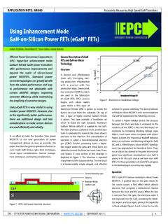
4 COSS Output Capacitance VGS = 0 V, VDS = 100 V CRSS Reverse Transfer Capacitance 135 163 pF. COSS(ER) Effective Output Capacitance,Energy Related (Note 1) 156. VGS = 0 V, VDS = 0 to 100 V. COSS(TR) Effective Output Capacitance,Time Related (Note 2) 201. RG Gate Resistance . QG Total Gate Charge VGS = 5 V, VDS = 100 V, ID = 7 A QGS Gate-to-Source Charge QGD Gate-to-Drain Charge VDS = 100 V, ID = 7 A nC. QG(TH) Gate Charge at Threshold QOSS Output Charge VGS = 0 V, VDS = 100 V 20 24. QRR Source-Drain Recovery Charge 0. # Defined by design. Not subject to production test. Figure 1: Typical Output Characteristics at 25 C Figure 2: Transfer Characteristics 45 45. 40 40. 25 C. 35 35 125 C. VGS = 5 V VDS = 6 V. 30 30. ID Drain Current (A). ID Drain Current (A). VGS = 4 V. VGS = 3 V.
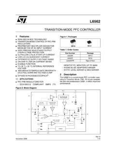
5 25 25. VGS = 2 V. 20 20. 15 15. 10 10. 5 5. 0 0. 0 1 2 3 4 5 6 VDS Drain-to-Source Voltage (V) VGS Gate-to-Source Voltage (V). Figure 3: RDS(on) vs. VGS for Various Drain Currents Figure 4: RDS(on) vs. VGS for Various Temperatures 120 120. 25 C. RDS(on) Drain-to-Source Resistance (m ). RDS(on) Drain-to-Source Resistance (m ). 100 ID = A 100 125 C. ID = A ID = 7 A. ID = A. 80 ID = A 80. 60 60. 40 40. 20 20. 0 0. VGS Gate-to-Source Voltage (V) VGS Gate-to-Source Voltage (V). EPC Power CONVERSION TECHNOLOGY LEADER | | 2022 | | 2. eGaN FET DATASHEET EPC2019 . Figure 5a: Typical Capacitance (Linear Scale) Figure 5b: Typical Capacitance (Log Scale). 450 1000. 400 COSS = CGD + CSD. CISS = CGD + CGS. 350 CRSS = CGD 100. 300. Capacitance (pF). Capacitance (pF). 250. 10 COSS = CGD + CSD.
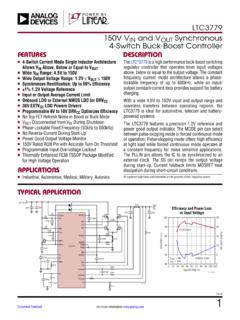
6 200 CISS = CGD + CGS. CRSS = CGD. 150. 1. 100. 50. 0 0 50 100 150 200 0 50 100 150 200. VDS Drain-to-Source Voltage (V) VDS Drain-to-Source Voltage (V). Figure 6: Typical Output Charge and COSS Stored Energy Figure 7: Typical Gate Charge 35 5. ID = 7 A. 28 4. VDS = 100 V. VGS Gate-to-Source Voltage (V). EOSS COSS Stored Energy ( J). QOSS Output charge (nC). 21 3. 14 2. 7 1. 0 0. 0 0 50 100 150 200. QG Gate Charge (nC). VDS Drain-to-Source Voltage (V). Figure 8: Reverse Drain-Source Characteristics Figure 9: Normalized On-State Resistance vs. Temperature 45 40. 25 C. Normalized On-State Resistance RDS(on). 35 125 C ID = 7 A. ISD Source-to-Drain Current (A). VGS = 0 V VGS = 5 V. 30. 25. 20. 15. 10 5. 0 0 4 .0 0 25 50 75 100 125 150. VSD Source-to-Drain Voltage (V) TJ junction Temperature ( C).
7 All measurements were done with substrate shortened to source. EPC Power CONVERSION TECHNOLOGY LEADER | | 2022 | | 3. eGaN FET DATASHEET EPC2019 . Figure 10: Normalized Threshold Voltage vs. Temperature Figure 11: Safe Operating Area 100. ID = mA. Normalized Threshold Voltage (V). ID Drain Current (A). 10. Limited by RDS(on). 1. Pulse Width 100 ms 100 s 10 s 1 10 100 1000. 0 25 50 75 100 125 150. VDS Drain-Source Voltage (V). TJ junction Temperature ( C). TJ = Max Rated, TC = +25 C, Single Pulse Figure 12: Transient Thermal Response Curves junction -to-Board 1. Duty Cycle: Z JB, Normalized Thermal Impedance PDM. t1. t2. Notes: Duty Factor: D = t1/t2. Single Pulse Peak TJ = PDM x Z JB x R JB + TB. 10-5 10-4 10-3 10-2 10-1 1 10+1. t1, Rectangular Pulse Duration, seconds junction -to-Case 1.
8 Duty Cycle: Z JC, Normalized Thermal Impedance PDM. t1. t2. Notes: Single Pulse Duty Factor: D = t1/t2. Peak TJ = PDM x Z JC x R JC + TC. 10-6 10-5 10-4 10-3 10-2 10-1 1. t1, Rectangular Pulse Duration, seconds EPC Power CONVERSION TECHNOLOGY LEADER | | 2022 | | 4. eGaN FET DATASHEET EPC2019 . TAPE AND REEL CONFIGURATION. 4 mm pitch, 8 mm wide tape on 7 reel d e f g Loaded Tape Feed Direction 7 reel Die b orientation ZZZZ dot c Gate a YYYY. solder bar is 2019 under this corner Die is placed into pocket solder bar side down DIM Dimension (mm) (face side down). EPC2019 (Note 1) Target MIN MAX. a b c (Note 2) d Note 1: MSL 1 (moisture sensitivity level 1) classified according to IPC/. e JEDEC industry standard. f (Note 2) Note 2: Pocket position is relative to the sprocket hole measured as g true position of the pocket, not the pocket hole.
9 DIE MARKINGS. 2019. Laser Markings YYYY Part Die orientation dot Number Part # Lot_Date Code Lot_Date Code ZZZZ Marking Line 1 Marking Line 2 Marking Line 3. Gate Pad bump is EPC2019 2019 YYYY ZZZZ. under this corner A. DIE OUTLINE MICROMETERS. f DIM. Solder Bar View X3 MIN Nominal MAX. A 2736 2766 2796. k 2 6 B 920 950 980. d 3 4 5 c 697 700 703. B. c h d 247 250 253. 1 7. e 168 183 198. f 245 250 255. e g g X4 X2 g 600 600 600. h 450 450 450. i 235 250 265. 815 Max Side View (685). Pad is Gate;. Pad no. 3, 5 are Drain;. Pad no. 2, 4, 6 are Source;. 100 20. Seating plane Pad no. 7 is Substrate.*. *Substrate pin should be connected to Source EPC Power CONVERSION TECHNOLOGY LEADER | | 2022 | | 5. eGaN FET DATASHEET EPC2019 . RECOMMENDED. LAND PATTERN 2766 The land pattern is solder mask defined.
10 (measurements in m) 600 600 Copper is larger than the solder mask opening. X4 X2. Solder mask is 10 m smaller per side than bump. 1 7. 230. X4. Pad no. 1 is Gate 950. 3 4 5. 450. 680. Pad no. 3, 5 are Drain X2. 2 6 Pad no. 2, 4, 6 are Source Pad no. 7 is Substrate*. X4 X3. 230 230. *Substrate pin should be connected to Source RECOMMENDED. STENCIL DRAWING Recommended stencil should be 4 mil (100 m). (units in m) 2766 thick, must be laser cut , opening per drawing. 600 600. X4 X2 The corner has a radius of R60. 1 7. 230. X4. Intended for use with SAC305 Type 3 solder, 950. 3 4 5. 450. 680. reference metals content X2. 2 6. X4 X3. 230 230. Additional Resources Available Assembly resources available at: Library of Altium footprints for production FETs and ICs: (for preliminary device Altium footprints, contact EPC).