Transcription of Fundamentals of Gallium Nitride Power Transistors
1 APPLICATION NOTE: AN002 GaN Power TransistorsEPC Power CONVERSION TECHNOLOGY LEADER | | 2020 | | 1 OperationEPC s enhancement mode Gallium Nitride (eGaN ) Transistors behave very similarly to silicon Power MOSFETs. A positive bias on the gate relative to the source causes a field effect which attracts electrons that complete a bidirectional channel between the drain and the source. A key difference between Gallium Nitride (GaN) and silicon is that the electrons in the 2 DEG are not associated to any particular atom, as opposed to being loosely trapped in a lattice, they have an equal probability of being anywhere in the plane.
2 The result is a channel of resistance much lower than that of silicon. When the bias is removed from the gate, the electrons under it are dispersed into the GaN, recreating the depletion region, and once again, giving it the capability to block voltage. StructureA device s cost effectiveness starts with leveraging existing production infrastructure. EPC s manufacturing utilizes standard CMOS tools to fabricate their devices. EPC s process begins with silicon wafers. Using an MOCVD reactor, a thin layer of aluminum Nitride (AlN) is grown on the silicon to transition the crystal from silicon to GaN.
3 This is a seed layer used to grow a thick layer of highly resistive GaN on the silicon wafer. GaN is a wide bandgap material that can support high voltage at small distances. The GaN layer provides a foundation on which to build the GaN transistor. An aluminum Gallium Nitride (AlGaN) layer is deposited resulting in a piezoelectric polarization, with an abundance of electrons being generated just below the AlGaN that is highly conductive. This abundance of electrons is known as a two dimensional electron gas (2 DEG).Further processing forms a depletion region under the gate.
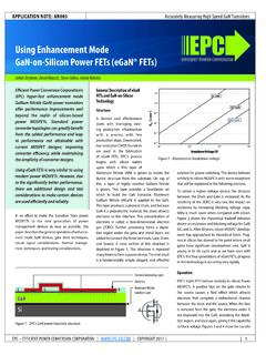
4 To enhance the transistor, a positive voltage is applied to the gate in the same manner as turning on an n-channel, enhancement mode Power MOSFET. A cross section of this structure is depicted in figure 1. This structure is repeated many times to form a Power device. The end result is a fundamentally simple, elegant, cost effective solution for Power switching. This device behaves similarly to silicon MOSFETs with some exceptions that will be explained in the following obtain a higher voltage device, the distance between the Drain and Gate is increased. As the resistivity of GaN 2 DEG is very low, the impact on resistance by increasing blocking voltage capability is much lower when compared with silicon.
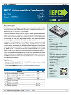
5 Figure 2 shows the theoretical resistance times die area limits of GaN versus silicon versus voltage. EPC s fifth generation of devices is shown as well. Please note that after 30 years of MOSFET development, silicon has approached its theoretical limits. Progress in silicon has slowed to the point where small gains have significant development cost. GaN is young in its life cycle, and will see significant improvement in the years to of Gallium Nitride Power TransistorsStephen L. Colino and Robert A. Beach, basic requirements for Power semiconductors are efficiency, reliability, controllability, and cost effectiveness.
6 High frequency capability adds further value in size and transient response in regulators, and fidelity in class D amplifiers. Without efficiency and reliability, a new device structure would have no chance of economic viability. There have been many new structures and materials considered; some have been economic successes, others have seen limited or niche acceptance. Breakthroughs by EPC in processing Gallium Nitride have produced enhancement mode devices with high conductivity and hyper fast switching, with a silicon-like cost structure and fundamental operating mechanism.
7 SiSGDGaNElectron generating layerDielectricAluminum nitrideisolation layerEFFICIENT Power CONVERSIONEPC2215 GaN Limit10110010-110-210-310-4101102103104 SiC LimitSi Limit100 VBreakdown Voltage (V)200 VSpeci c RDS(on) ( mm2)EPC2218 Figure 2. Theoretical resistance times die area limits GaN vs. silicon vs. voltageFigure 1. EPCs GaN Power Transistor StructureAPPLICATION NOTE: AN002 GaN Power TransistorsEPC Power CONVERSION TECHNOLOGY LEADER | | 2020 | | 2 Gate ThresholdThe threshold of Gallium Nitride Transistors is lower than that of silicon MOSFETs. This is made possible by the almost flat relationship between threshold and temperature along with the very low CGD, as described later.
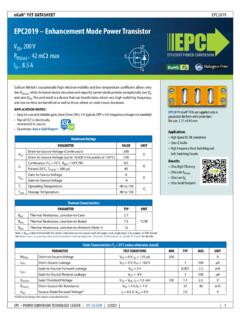
8 Figure 3 shows the transfer characteristics curve for the EPC2218, 100 V, m (max) transistor. Please note the negative relationship between current and temperature. This provides for excellent sharing all regions of operation, which will be explained later. Even with significant conduction current above V, The Ratio of QGD to QGS(th) is indicating that the device will be held off regardless of (on) versus VGS curves are similar to MOSFETs. EPC fifth generation GaN Transistors are designed to operate with 5 V drive. Figure 4 shows the set of curves for the EPC2218. The curve shows that RDS(on) flattens as the absolute maximum gate voltage is approached.
9 As there is negligible gate drive loss penalty, GaN Transistors should be driven with 5 V. The temperature coefficient of RDS(on) of the GaN transistor is also similar to the silicon MOSFET as it is positive with about the same magnitude or of the 25 C point at 100 C point for the In addition to the low RDS(on), the lateral structure of the GaN transistor makes it a very low charge device as well. It has the capability of switching hundreds of volts in nanoseconds, giving it multiple megahertz capability. This capability will lead to smaller Power converters, and higher fidelity class D amplifiers.
10 Most important in switching is CGD. With the lateral structure, CGD comes only from a small corner of the gate. An extremely low CGD leads to the very rapid voltage switching capability of GaN consists of the junction from the gate to the channel, and the capacitance of the dielectric between the gate and the field plate. CGD is very small when compared with CGS, giving GaN Transistors excellent dv/dt immunity. CGS still small when compared with silicon MOSFETs giving them very short delay times, and excellent controllability in low duty cycle applications.