Transcription of Execute in Place (XIP) with Quad SPI Interface
1 SMART ARM-based MCUs Execute in Place (XIP) with Quad SPI Interface (QSPI) APPLICATION NOTEI ntroductionThis application note describes the Execute In Place (XIP) feature of QSPIand its implementation in Atmel | SMART SAM V71/V70/E70/S70 also explains how to generate binary to Execute in QSPI region and how toexecute an application from Features Master SPI Interface Programmable Clock Phase and Clock Polarity Programmable Transfer Delays Between Consecutive Transfers,Between Clock and Data, Between Deactivation and Activationof Chip Select SPI Mode Interface to Serial Peripherals such as ADCs, DACs, LCDC ontrollers, CAN Controllers and Sensors 8-bit/16-bit/32-bit Programmable Data Length Serial Memory Mode Interface to Serial Flash Memories Operating in Single-bit SPI,Dual SPI and Quad SPI Supports Execute In Place (XIP)
2 Code Execution by theSystem Directly from a Serial Flash Memory Flexible Instruction Register for Compatibility with All Serial FlashMemories 32-bit Address Mode (default is 24-bit address) to Support SerialFlash Memories Larger than 128 Mbit Continuous Read Mode Scrambling/Unscrambling "On-The-Fly" Connection to DMA Channel Capabilities Optimizes Data Transfers One channel for the Receiver, One Channel for the Transmitter Register Write ProtectionAtmel-44065A- Execute -in- Place - XIP-with-Quad-SPI- Interface -SAM-V7-SAM-E 7-SAM-S7_Application Note-01/2016 Table of V71 Xplained Ultra Evaluation V71 / V70 / E70 / S70 Software Studio Version SP2 or Software Framework (ASF).. SAM-BA In-system Programmer (Version or Later).. to SPI Serial Memory Frame In Place (XIP).. in SAM S7/SAM E7/SAM V7 Configuration for QSPI.
3 Binary for QSPI Memory Region .. Linker Script Linker File an Application in QSPI from External Serial Flash Memory Using QSPI XIP QSPI Support to an Existing Application in the Software Source Code in Software QSPI Support to an Existing Application in Source Code in Example an Application to QSPI Using of QSPI in XIP Performance in Structure Impact to QSPI Access Way Impact to QSPI Asked Questions [FAQ].. we boot from QSPI memory?.. is the maximum size of the serial Flash memory connected over QSPI?.. is the recommended MPU setting for QSPI region?.. is the maximum data rate of the Quad I/O Serial Peripheral Interface (QSPI)?.. Execute in Place (XIP) with Quad SPI Interface (QSPI) [APPLICATION NOTE]Atmel-44065A- Execute -in- Place -XIP-w ith-Quad-SPI- Interface -SAM-V7-SAM-E7-SAM -S7_Application Note-01 | SMART SAM S7/SAM E7/SAM V7 Documentation on Cortex-M7.
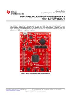
4 Application User Manual .. Execute in Place (XIP) with Quad SPI Interface (QSPI) [APPLICATION NOTE]Atmel-44065A- Execute -in- Place -XIP-w ith-Quad-SPI- Interface -SAM-V7-SAM-E7-SAM -S7_Application Note-01/201631. Hardware/Software RequirementsThe following hardware and software environment is needed to evaluate the SAM V71 Xplained Ultra Evaluation KitThe Atmel | SMART SAM V71 Xplained Ultra Evaluation Kit is ideal for evaluating and prototyping theAtmel ARM Cortex -M7-based microcontrollers in the SAM V71, SAM V70, SAM S70 and SAM E70series. The SAM V71-XULT evaluation kit does not include extension boards. The extension boards canbe purchased individually. Here is a detailed view of the SAM V71 Xplained Ultra Evaluation 1-1. SAM V71 Xplained Ultra Evaluation KitInfo: Atmel web page for the SAM V71 Xplained Ultra Evaluation Kit: Execute in Place (XIP) with Quad SPI Interface (QSPI) [APPLICATION NOTE]Atmel-44065A- Execute -in- Place -XIP-w ith-Quad-SPI- Interface -SAM-V7-SAM-E7-SAM -S7_Application Note-01/20164 Info: User Guide: : Schematics: SAM V71 / V70 / E70 / S70 Software PackageThe software package provides basic drivers, software services, libraries for Atmel | SMART SAM V71,SAM V70, SAM E70, SAM S70 ARM Cortex-M7-based microcontrollers.
5 It contains source code, usageexamples, documentation, and ready-to-use projects for Atmel Studio, GNU, IAR EWARM, and Keil : The application is demonstrated by using Software Package Version It is alwaysrecommended to download the latest version given in the link : Software Package: Atmel Studio Version SP2 or LaterAtmel Studio is the integrated development platform (IDP) for developing and debugging Atmel | SMARTARM-based and Atmel AVR microcontroller : Atmel Studio: Atmel Software Framework (ASF)The Atmel Software Framework (ASF) is an MCU software library providing a large collection ofembedded software for Atmel Flash MCUs: megaAVR, AVR XMEGA, AVR UC3 and SAM devices. ASF isintegrated in the Atmel Studio IDE with a graphical user Interface or available as standalone for GCC, IARcompilers. ASF can be downloaded for : ASF: Execute in Place (XIP) with Quad SPI Interface (QSPI) [APPLICATION NOTE]Atmel-44065A- Execute -in- Place -XIP-w ith-Quad-SPI- Interface -SAM-V7-SAM-E7-SAM -S7_Application Note-01 Atmel SAM-BA In-system Programmer (Version or Later)Atmel SAM-BA software provides an open set of tools for programming the ARM : SAM-BA: Execute in Place (XIP) with Quad SPI Interface (QSPI) [APPLICATION NOTE]Atmel-44065A- Execute -in- Place -XIP-w ith-Quad-SPI- Interface -SAM-V7-SAM-E7-SAM -S7_Application Note-01/201662.
6 Introduction to QSPIThe Quad SPI Interface (QSPI) is a synchronous serial data link that provides communication withexternal devices in Master mode. It is similar to SPI protocol except that it has additional data normal SPI has four communication lines: Chip Select, Clock, MOSI, and MISO. For QSPI, additionaldata lines are available. So the command/data/address are sent through single, quad or dual IO based onthe mode selected. As data is sent over multiple lines, it helps in increasing bandwidth compared tostandard SPI 2-1. QSPI Block DiagramIn SAM S7/SAM E7/SAM V7 devices, QSPI can be used in normal SPI mode or in Serial Memory modeto connect to external Flash memories. To activate the modes, the SMM bit in the Mode register(QSPI_MR) needs to be configured operates on the clock controlled by the internal programmable baud rate generator.
7 Clock phaseand polarity can be configured in the Serial Clock register (QSPI_SCR). The delays listed below areprogrammable via QSPI_MR. These delays allow the QSPI to be adapted to the interfaced peripheralsbased on their speed and timing. Transfer Delays between Consecutive Transfers Delay between Clock and Data Delay between Deactivation and Activation of Chip SelectInfo: In the following sections, the terms 'serial memory', 'serial Flash memory', 'external Flashmemory' refer to the external serial Flash memory connected over QSPI SPI modeThe QSPI can be used in SPI mode to Interface to serial peripherals (such as ADCs, DACs, LCDcontrollers, CAN controllers and sensors).In SPI mode, the QSPI acts as a regular SPI Master. To activate this mode, the bit SMM must be clearedin Execute in Place (XIP) with Quad SPI Interface (QSPI) [APPLICATION NOTE]Atmel-44065A- Execute -in- Place -XIP-w ith-Quad-SPI- Interface -SAM-V7-SAM-E7-SAM -S7_Application Note-01/20167 The QSPI features two holding registers: Transmit Data register (QSPI_TDR) Receive Holding register (QSPI_RDR)Once enabled, the QSPI_TDR holds the data to be transferred.
8 After data is written to QSPI_TDR, itimmediately gets shifted to the internal shift register and starts transferring on the MOSI line. When theinternal register shifts data on the MOSI line, the MISO line is sampled and stored to QSPI_RDR. IfReceiving mode is not needed, the receive status flag in the Status register (QSPI_SR) can be can be generated and DMA can be used for optimized to the product datasheet for a detailed description of the operation and configuration of the QSPI inSPI QSPI Serial Memory ModeIn Serial Memory mode, the QSPI acts as a serial Flash memory controller. To activate this mode, theSMM bit must be set in the QSPI_MR. Once enabled, the peripheral appears as memory-mapped deviceat QSPI memory space 0x8000_0000. The data is read or written to the address 0x8000_0000 in SerialMemory mode. In this mode, the data cannot be transferred by the QSPI_TDR or QSPI can be used to read data from the serial Flash memory allowing the CPU to Execute code fromit (XIP Execute in Place ).
9 The QSPI can also be used to control the serial Flash memory (Program, Erase,Lock, etc.) by sending specific commands. In Serial Memory mode, the QSPI is compatible with thefollowing modes: Single-Bit SPI Dual SPI Quad Single-Bit SPIIn Single-Bit SPI mode, the communication with external Flash is done via either MOSI or MISO 2-2. Single-Bit Dual SPIIn Dual SPI mode, QSPI master communicates with the external memory through two bidirectional Execute in Place (XIP) with Quad SPI Interface (QSPI) [APPLICATION NOTE]Atmel-44065A- Execute -in- Place -XIP-w ith-Quad-SPI- Interface -SAM-V7-SAM-E7-SAM -S7_Application Note-01/20168 Figure 2-3. Dual Quad SPIIn Quad SPI mode, all four IO lines are used for communication with the external 2-4. Quad SPIIn SAM S7/SAM E7/SAM V7 devices, the command, address and data can be sent independently usingdifferent modes.
10 The configuration is done in QSPI Instruction Frame register (QSPI_IFR) based on theserial memory connected over QSPI. The available configurations are listed 2-5. Available SPI Modes in Serial Memory Instruction Frame StructureTo control the external Flash memories, the QSPI is able to send instructions via the SPI bus foroperations such as READ, WRITE, PROGRAM, ERASE, LOCK, etc. The instruction set supported by theserial Flash memories is includes an Instruction Frame register (QSPI_IFR) for this purpose which makes it flexible andcompatible with all serial Flash memories. An Instruction Frame includes the fields Execute in Place (XIP) with Quad SPI Interface (QSPI) [APPLICATION NOTE]Atmel-44065A- Execute -in- Place -XIP-w ith-Quad-SPI- Interface -SAM-V7-SAM-E7-SAM -S7_Application Note-01/20169 Figure 2-6. Instruction Frame StructureA typical instruction frame in Quad SPI mode is illustrated Instruction Frame ConfigurationThe Instruction frame needs to be configured based on the commands to be sent to the external Flashmemory.


