Transcription of Experiment #1 - The Digital Multimeter
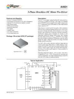
1 EECS40/43 DMM. Experiment - The Digital Multimeter I. Objective To become familiar with a Digital Multimeter (DMM) and how it works. At the same time to become familiar with resistors and to learn how to use a power supply. II. Review of Basic Concepts resistor : A resistor is schematically shown in Fig. 1. Its characteristic equation is given by Ohm's Law: V = IR. +. I R V. _. Figure 1. Voltage source: The circuit symbol for a voltage source is shown in Fig. 2. Its one characteristic is that the voltage across its terminals is always V volts, no matter what the current going through it is. V +_. Figure 2. Current source: Page 1. EECS40/43 DMM. The circuit symbol for a current source is shown in Fig. 3. Its one characteristic is that the current through it is always I amps, no matter what the voltage across it is. I. Figure 3. Series connection (see Fig. 4): This is when the devices are connected in such a way that both devices have the same current flowing through them.
2 V1 _. +. I1. Device 1. +. I2 V2. Device 2. _. Figure 4. I1 = I2. Page 2. EECS40/43 DMM. Parallel connection (see Fig. 5): This is when the devices are connected in such a way that they have the same voltage across them. + +. I1 V1 I2 V2. Device 1 Device 2. _ _. Figure 5. V1 = V2. Resistors connected in series (see ): I1. V1 _. +. R1 + +. IX IX. + +. VX _ R2 V2 I2 VX _ Req V1 + V2 I2. _ _. Figure 6. Ix = I1 = I2. V x =i x R1 + i x R2. Vx = Req = R1 + R2. ix Page 3. EECS40/43 DMM. Resistors connected in parallel (see ): IX IX. + + +. I1+I2. VX. + VX. +. _ R1 I1 V1 R2 I2 V2 _ Req V1. _ _ _. Figure 7. Vx V. i1 = , i2 = x R1 R2. i x = i1 + i 2. Vx Vx ix = +. R1 R2. 1 1 i 1. + = x =. R1 R2 Vx Req Voltage divider (see Fig. 6): V x = i x R1 + i x R2. V1 = i x R1 ,V2 = i x R2. V2 i x R2. =. V x i x ( R1 + R2 ). R2. V2 = V x R1 + R2. R1. V1 = V x R1 + R2. Thevenin equivalent circuit: Every circuit which consists of voltage sources, current sources and resistors can be represented with a Thevenin equivalent circuit.
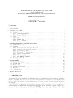
3 The form of the equivalent circuit is shown in Fig. 8a and the I-V characteristic is shown in 8b. The open circuit voltage is denoted as Voc; the short circuit current is denoted as Isc and the Thevenin resistance is denoted as Rt. Voc = I sc Rt The values of Voc, Isc and Rt can be determined by measuring the I-V. characteristic of a circuit and extracting the parameters from the graph. Page 4. EECS40/43 DMM. IT. IT. + ISC Slope = -1/R. RT. VOC. +. _ VV. T2 VT. VOC. _. a) IT b). Figure 8. III. Operation The DMM is an instrument which can be used to measure DC (non-time-varying). voltages and currents, AC (time-varying) voltages and currents, and resistance values. The signal is input to the DMM through two leads (wires), and the value measured is displayed. The DMM uses an A/D (analog-to- Digital ) converter, which converts DC voltages to a Digital code. Therefore, internally the meter can read only DC voltages.
4 Thus to measure current or resistance , the signal must be converted into a voltage value. For current, this is easily done by placing a (very small) precision resistor in the circuit and measuring the voltage across the resistor , which will be linearly proportional to the current (remember Ohm's Law: V=IR). resistance measurements require more circuitry because a resistor is a passive element, thus a source must be provided in the DMM. In the DMM there is a current source to force a current through the resistor and the voltage is then measured. From this information the resistance value may be determined by Ohm's Law: V. R=. I. Additional circuitry is necessary to allow variable ranges. For voltage and resistance measurements this consists of various voltage-divider networks which are switched in. For current measurements it consists of different resistors to be switched in. Also, an RMS (root mean square) circuit is used to convert the AC voltages to DC voltages.
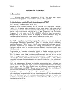
5 The DC voltage given is the square root of the average value of the input voltage squared. VOUT = < (V IN ) 2 >. Page 5. EECS40/43 DMM. The DC voltage is converted into a Digital code by the A/D converter. This Digital code is decoded using the range of information and displayed. Since a voltmeter measures the voltage across itself, it should be connected in parallel (see Fig 9a) with the device to guarantee that the voltage across the device under test (DUT) is the same as the voltage across the voltmeter. An ammeter measures the current through itself, so it should be connected in series (see Fig 9b) with the DUT in order to ensure that the current through the ammeter is the same as the current through the DUT. An ohmmeter sends out a current and measures the voltage produced across the DUT. Because the ohmmeter is ultimately measuring a voltage, it should be connected in parallel (see Fig 9c) with the DUT.
6 When measuring a resistance , one end of the resistor should be disconnected from the circuit so that all of the current from the DMM's current source is passing through the resistor to be measured. Otherwise one is not measuring the resistance value of the resistor because the current going through the resistor is unknown. Voltmeter DUT. DUT. Ammeter a) b). Ohmeter Rest of DUT. Circuit c). Figure 9. IV. Multimeter Controls Page 6. EECS40/43 DMM. There is a diagram of the front of the Multimeter given in Fig. 10. V . HI. LO. I. Figure 10. To measure voltage: 1. use the right ports labeled HI and LO (see Fig. 10). 2. choose either AC or DC voltage by hitting the AC V or the DC V key 3. connect the DMM in parallel as shown in Fig. 10a 4. adjust the range of the measurement using the level up and down keys V . HI. DC. LO. I. Figure 10a To measure current: 1. use the right ports labeled I and LO (see Fig 10).
7 2. choose either AC or DC current by hitting shift AC V (AC I) or the shift DCV. (DC I) key 3. connect the DMM in series as shown in Fig. 10b 4. adjust the range of the measurement using the level up and down keys V . HI. LO. DC. I. Figure 10b Page 7. EECS40/43 DMM. To measure resistance 1. use the right ports labeled HI and LO (see Fig 10). 2. choose resistance by hitting the 2W key 3. connect the DMM in parallel with the resistor disconnected as shown in Fig. 9c 4. adjust the range of the measurement using the level up and down keys Note: Be very careful that when set up to measure current you don't put the DMM in parallel with the voltage source (see Fig. 11). The wrong way will blow the fuse in the Multimeter . This is because of the small resistance of the ammeter (Ra). The resistance seen by the voltage source is approximately Ra, which is very small so the current Ia would be very large, thus exceeding the maximum current that the fuse can handle.
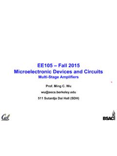
8 + DC Power Ammeter _. Supply Figure 11. V. DC Voltage Supply Controls The voltage source that we have actually contains three variable voltage sources, with maximum voltage values of +25V, -25V and 6V (see Fig. 12 for a diagram of the three sources and the power supply connections). To set a voltage source: 1. Make sure that the supply's output is off. This can be toggled by hitting the output on/off key. The display will say OUTPUT OFF when it is off or it will display the output voltage and current. 2. Select which source you would like to set, the +25V, the 25V or the +6V by hitting the corresponding key on the supply. The supply you have selected will be displayed along the bottom of the display screen. 3. Then hit the display limit key. You will know that you are changing the limit because LMT will be displayed along the bottom of the display. 4. Select to set the voltage or current limit by hitting the voltage/current key.
9 The one that is blinking is the one that you are editing. 5. When done setting the limits, hit the display limit key again to return to displaying the actual output. 6. Turn the output on once you have connected the supply to the circuit. Page 8. EECS40/43 DMM. Front of the DC power supply _. + +25V com -25V. +6V. + + 25V. + +. 6V _ 25V _. _. com _. 25V. +. -25V. Figure 12. VI. Hands On a. resistance Read Appendix 1 to review the color coding of resistors. Turn the meter on and set it up to measure resistance in the manner explained above. Measure the resistance of a 1k resistor . Initially have the meter set on auto ranging ( the word MAN is not lit up on the bottom of the display). The value will not be exactly what is marked on the resistor because they are built to a specific tolerance. Then adjust the range as described above (adjusting the range will set the meter to manual scaling).
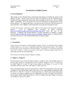
10 Get another resistor and measure its resistance . Hook the two resistors in series, predict what the measured value should be, measure it. If it disagrees by more than 10%, try again. If the measurement is still too far off, get help. Connect the two resistors in parallel, predict the resistance value, and measure it. Page 9. EECS40/43 DMM. Again confirm that the measured value is reasonable considering the resistor tolerances. A potentiometer (pot) is a variable resistor . It has a constant resistance between pins 1. & 3 (see Fig. 13) and the knob controls the resistance between pins 1 & 2 and 2 & 3. Circuit Real Pot Real Pot Symbol Top View 1. Knob 1. 3 1 2. 2. 123 3. Knob Figure 13. Measuring the resistance of the potentiometer (only connect one leg at a time). 1. With the dial of the pot facing you and the legs pointing down, what is the resistance between the two outside legs?